
Page 138 - Modern Control Systems
P. 138
112 Chapter 2 Mathematical Models of Systems
R
-
o W V •AAAr +
I lis) > I 2(s)
VAs) V ?<R C
(a)
v,Q ••
L, = -GR = - 1
-
L, = G/?= - 1
(b)
O—
VAs) V^s)
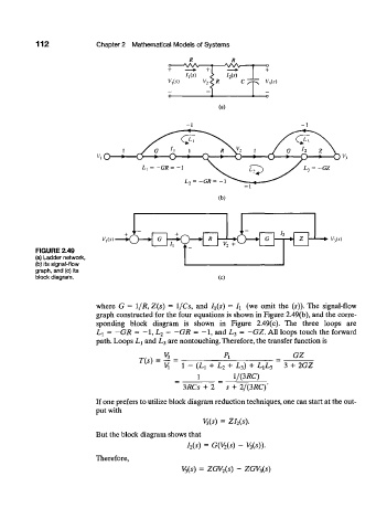
FIGURE 2.49
(a) Ladder network,
(b) its signal-flow
graph, and (c) its
block diagram. (c)
where G = 1/R, Z(s) = l/Cs, and ^(s) = I x (we omit the (5)). The signal-flow
graph constructed for the four equations is shown in Figure 2.49(b), and the corre-
sponding block diagram is shown in Figure 2.49(c). The three loops are
-
= -GR = 1 , = -GR = 1 , = -GZ. All loops touch the forward
-
L t L 2 and L 3
path. Loops Li and L 3 are nontouching. Therefore, the transfer function is
GZ
T(s) =
1 - (Lj + L 2 + L 3) + L rL 3 3 + 2GZ
1 = 1/&RC)
3RCs + 2 s + 2/(3RC)'
If one prefers to utilize block diagram reduction techniques, one can start at the out-
put with
V 3(s) = ZI 2(s).
But the block diagram shows that
I 2(s) = G(V 2(s) - V 3(s)).
Therefore,
V 2(s) = ZGV 2(s) - ZGV 3(s)