
Page 288 - Modern Control Systems
P. 288
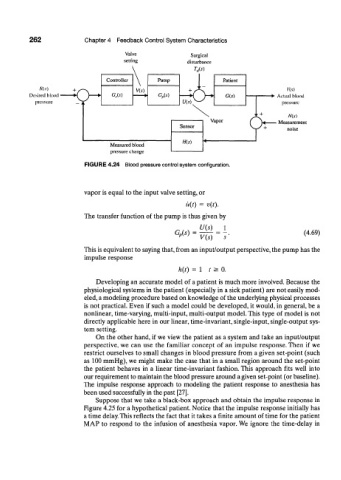
262              Chapter 4  Feedback  Control System  Characteristics

                                       Valve               Surgical
                                       setting            disturbance
                                                            w
                                  Controller     Pump
                       o-
             R(s)                          \                                             Y(s)
          Desired  blood           G c(s)        G p(s)                             •  Actual blood
            pressure                                                                   pressure


                                                                                 4    Measurement


                                   Measured blood
                                   pressure change
                           FIGURE 4.24  Blood pressure control system configuration.


                           vapor is equal to the input valve setting, or
                                                          u(t)  =  v(t).

                           The transfer  function  of the pump is thus given by
                                                              U(s)   1
                                                      GM    =                                 (4.69)
                                                              V(s)
                           This is equivalent to saying that, from  an input/output perspective, the pump has the
                           impulse response

                                                        h{t)  =  1  t  >  0.
                              Developing an accurate model of a patient is much more involved. Because the
                           physiological systems in the patient  (especially in a sick patient) are not easily mod-
                           eled, a modeling procedure based on knowledge of the underlying physical processes
                           is not  practical. Even  if such a model could be developed, it would, in general, be a
                           nonlinear, time-varying, multi-input, multi-output  model. This type  of model is not
                           directly applicable here in our linear, time-invariant, single-input, single-output sys-
                           tem setting.
                              On the other hand, if we view the patient  as a system and take an input/output
                           perspective, we  can  use  the  familiar  concept  of  an  impulse  response. Then  if  we
                           restrict ourselves to small changes in blood pressure from  a given set-point  (such
                           as  100 mmHg), we might make the case that in a small region around the  set-point
                           the  patient  behaves  in  a linear  time-invariant  fashion. This  approach  fits  well into
                           our requirement to maintain the blood pressure around a given set-point (or baseline).
                           The  impulse  response  approach  to  modeling  the  patient  response  to  anesthesia  has
                           been used successfully  in the past [27].
                              Suppose that we take a black-box approach  and obtain the impulse response in
                           Figure 4.25 for a hypothetical patient. Notice that the impulse response initially has
                           a time delay. This reflects the fact that it takes a finite  amount  of time for the patient
                           MAP to  respond  to the  infusion  of  anesthesia  vapor. We ignore  the  time-delay  in