
Page 312 - Modern Control Systems
P. 312
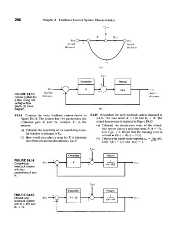
286              Chapter 4  Feedback Control System  Characteristics


                                            R(s) O                            Y(s)
                                         Desired                              Actual
                                        lliickness                            thickness


                                                             (a)

                                                              W
                                                  Controller             Process
                                                              +  i r  s  ,
                              R(s)       ^     ,     K                    G(5)             n.v)
                            Desired      i                - <   J    '
          FIGURE E4.13                                                                     Actual
          Control system for   thickness                                                   thickness
          a steel rolling mill.
          (a) Signal flow
          graph, (b) Block
          diagram.                                           (b)
          E4.14  Consider  the  unity  feedback  system  shown  in  E4.15  Reconsider  the  unity feedback  system discussed  in
              Figure  E4.14. The  system  has  two  parameters,  the  E4.14. This  time  select  K  =  120  and  K x  =  10. The
              controller  gain  K  and  the  constant  X,  in  the  closed-loop system is depicted  in Figure E4.15.
              process.                                     (a)  Calculate  the  steady-state  error  of  the  closed-
                                                              loop system due  to a unit step input, R(s)  =  l/s,
              (a)  Calculate  the sensitivity  of  the closed-loop trans-  with  T d(s)  =  0.  Recall  that  the  tracking  error  is
                 fer  function  to changes in  K x.
                                                              defined  as E(s)  =  R(s)  -  Y(s).
              (b)  How  would  you  select  a value  for  K  to  minimize  (b)  Calculate the steady-state response, y ss  =  limy(t),
                 the effects  of external disturbances, T (i{s)7   when  T a(s)  =  l/s  and  R(s)  =  0.  f ^°°

                                                       7 »
                                          Controller
                                                       +
          FIGURE E4.14
          Closed-loop      /?(.V) '          K        ^                         *>  Y(s)
          feedback system
          with two
          parameters, K and
          Kv

                                                       7- (/(.v)


          FIGURE E4.15
          Closed-loop
          feedback system
          withK  =  120 and
          /C, = 10.