
Page 314 - Modern Control Systems
P. 314
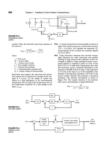
288             Chapter 4  Feedback Control System  Characteristics


                                                                              Environment


          FIGURE P4.3
          Temperature control
          system.                                  "desired

             actuator. Then  the  linearized  open-loop  response  of  P4.4  A control system  has two forward  paths, as shown  in
             the system is                                 Figure P4.4. (a) Determine  the overall transfer  function
                                                           7(5)  =  Y(s)/R(s).  (b)  Calculate  the  sensitivity,  S£,
                      ST(s)  =  ,  E(s)  +                 using Equation  (4.16). (c) Does the sensitivity  depend
                            TS  +  1   TS  +  1'           on U(s) or M(*)?
             where                                     P4.5  Large  microwave  antennas  have  become  increas-
                                                           ingly  important  for  radio  astronomy  and  satellite
                T  =  MC/( PA),                            tracking. A large antenna with a diameter  of 60 ft, for
                M  =  mass  in tank,                       example, is subject  to large wind  gust torques. A pro-
                A  =  surface  area  of tank,              posed  antenna  is  required  to  have  an  error  of  less
                p =  heat  transfer  constant,             than  0.10°  in a 35 mph  wind. Experiments  show  that
                C  =  specific  heat constant,             this wind force  exerts  a maximum  disturbance  at the
                k\  =  a dimensionality constant, and      antenna  of 200,000  ft  lb at  35 mph, or the  equivalent
                e tf,  =  output  voltage  of thermocouple.   to  10 volts  at  the  input  T (i(s) to  the  amplidyne. One
                                                           problem  of  driving  large  antennas  is the  form  of  the
             Determine  and  compare  the  open-loop  and  closed-
             loop systems for  (a) sensitivity  to changes  in the con-  system  transfer  function  that  possesses  a  structural
                                                           resonance.
                                                                   The
             stant  K  =  k\k aE b\  (b)  the  ability  to  reduce  the  Figure  P4.5. The antenna  servosystem  is  shown  in
                                                                                      of
                                                                               function
                                                                        transfer
                                                                                         the
                                                                                            antenna,
             effects  of  a  step  disturbance  in  the  environmental  drive motor, and amplidyne  is approximated  by
             temperature  A2T t .(i'); and  (c) the steady-state error  of
             the  temperature  controller  for  a  step  change  in  the        ,.?
             input, e desired.                                      G(s)  =             2
                                                                          s(.r  + 2£w„s +  (o „y
                                                   M(s)
                           R{s)            +  f~\                            n.v)
                                     U(s)           Q(s)
                           Inpul                          + ^~              Output
          FIGURE P4.4
         Two-path system.


                                                       TM)
                                                                                            0(s)
                                                                Antenna, drive motor,
                           /?(.v)                                                       - •  Position
                                                                 and amplidyne  G(s)
                                                                                          (radians)
          FIGURE P4.5
         Antenna control
          system.