
Page 319 - Modern Control Systems
P. 319
Advanced Problems 293
T t)(s) — A/s, determine the transient response of The model of the control system is shown in part (c),
T 2(t) when C c(s) = K = 500. (c) Find the steady- where K, 30. R f 1 0,, K f = K, = l,J = 0.1
state error e„ for the svstem of part (b). where and /) = 1. (a) Determine the response 9{t) of the sys-
B(s) = T M(s) - 7\(.v). tem to a step change in 0 d(l) when K = 20. (b) As-
suming 0,/(() = 0. find the effect of a load disturbance
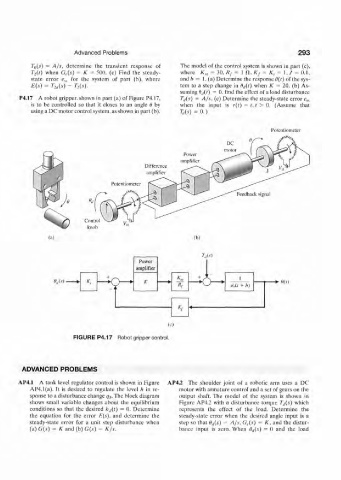
P4.I7 A robot gripper. shown in part (a) of Figure P4.17, T ti($) = A/s. (c) Determine the steady-state error e si
is to be controlled so that it closes to an angle t) by- when the input is r(t) = t,t > 0. (Assume that
using a DC motor control system, as shown in part (b). W = 0.)
Potentiometer
Difference
amplifier
(a) (b)
'/;,<*)
Power
amplifier
+ I
W K *\ o \(Js + />) -*- m
(0
FIGURE P4.17 Robot gripper control.
ADVANCED PROBLEMS
AP4.1 A tank level regulator control is shown in Figure AP4.2 The shoulder joint of a robotic arm uses a DC
AP4.1(a). It is desired to regulate the level h in re- motor with armature control and a set of gears on the
sponse to a disturbance change q$. The block diagram output shaft. The model of the system is shown in
shows small variable changes about the equilibrium Figure AP4.2 with a disturbance torque Tj(s) which
conditions so that the desired /7,,(/) = 0. Determine represents the effect of the load. Determine the
the equation for the error E{s), and determine the steady-slate error when the desired angle input is a
steady-state error for a unit step disturbance when step so that 6,i{s) = A/s, G c(s) = K, and the distur-
(a) G(.v) = K and (b) G(s) = K/s. bance input is zero. When fl rf(.v) = 0 and the load