Page 320 - Modern Control Systems
P. 320

294             Chapter 4  Feedback Control System  Characteristics

                                                             /i(/)
                                                    Controller

                                                         =¾       0=


                                                                     Orifice
                                             Capacitance  C
                                                                                      «o
                                                                   Constant  =  R
                                                               (a)


                                                                                  <?3(.v)
                            H d{s)  = 0             Controller
                            Desired      D   Error  >  G(.v)         /?Cv + :i                 H(s)
                                                                       J?
                             height      V   £ w                          1      + U          Height
                            variation   1                                                     variation
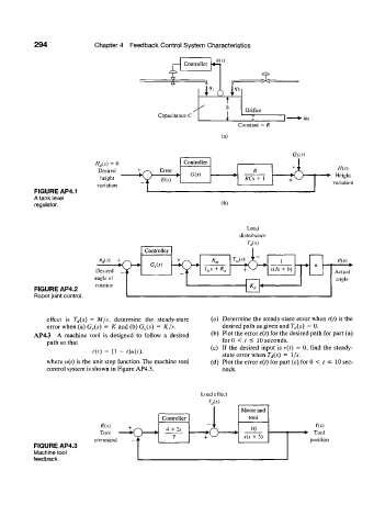
           FIGURE AP4.1
           A tank level
           regulator.                                          (b)


                                                                      Load
                                                                    disturbance

                                         Controller
                             W    ;  n  .  G,(.v)   "lO -         W   A-.      l         rt    0(s)
                                    J  w                  L as  + /?„       5(7.9 +  />)
                            Desired  _ j                             +                        Actual
                           angle of                                                            angle
                            rotation
           FIGURE  AP4.2                                               **
           Robot joint control.


              effect  is  T rI($)  =  M/s,  determine  the  steady-state  (a)  Determine the steady-state  error when  r(t)  is the
              error when (a) G e(s)  =  K and (b) G c(s)  =  K/S.  desired path as given and T d(s)  = 0.
           AP4.3  A  machine  tool  is  designed  to  follow  a  desired  (b)  Plot the error e{t) for the desired path for part (a)
              path so that                                     forO  <  t  =s 10 seconds.
                                                            (c)  If the desired  input  is r(t)  = 0, find  the  steady-
                           r(t)  =  (1  -  /)«(/),
                                                               state error when  T d(s)  =  l/s.
              where  u(t) is the unit  step function. The machine  tool  (d)  Plot the error e(t) for part (c) for 0  <  r  <  10 sec-
              control system is shown in Figure AP4.3.         onds.


                                                         Load  effect

                                                                    Motor and
                                              Controller              tool
                             R(s)                                                        Y(s)
                                                           o-
                                               4 +  2.v   b/           10
                             Tool                           C                        - •  Tool
                                                 7        +          s(s  + 5)
                           command                                                     position
           FIGURE AP4.3
          Machine tool
          feedback.
   315   316   317   318   319   320   321   322   323   324   325