
Page 321 - Modern Control Systems
P. 321
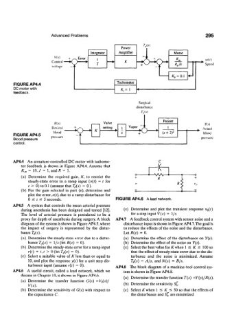
Advanced Problems                                                   295
                                                                 TJs)
                                                       Power
                                         Integrator   Amplifier
                                    Error   I
                        Control  — • ( >         — •    K
                                   )   *    s
                        voltage


                                                     Tachometer
       FIGURE AP4.4
       DC motor with                                   /:,=  1
       feedback.
                                                               Surgical
                                                              disturbance
                                                                7" (/ (.v)
                                                                          Patient
                                                                                            Y(s)
                                                                            1
                                                                                         w  Actual
                                                                         (s +  2) 2        blood
       FIGURE AP4.5
       Blood pressure                                                                     pressure
       control.


       AP4.4  An armature-controlled DC motor with tachome-
           ter  feedback  is  .shown  in  Figure  AP4.4. Assume  that  K
           K m  =  10./  =  l.andtf  =  1.
           (a)  Determine  the  required  gain,  K,  to  restrict  the  R
              steady-state  error  to  a ramp  input  (v(t)  =  t  for
              t  >  0) to 0.1 (assume that T d(s)  =  0).
           (b)  For  the  gain  selected  in  part  (a), determine  and
              plot  the error, e(t), due  to a ramp disturbance  for
              0  <  t  <  5 seconds.                 FIGURE AP4.6  A lead network.
       AP4.5  A system that  controls the  mean  arterial  pressure
           during  anesthesia  has been  designed  and  tested  [12].  (c)  Determine  and  plot  the  transient  response  u 0 (0
           The  level  of  arterial  pressure  is  postulated  to  be  a  for a step input V(s)  =  1/s.
           proxy for depth  of anesthesia  during surgery. A  block  AP4.7  A feedback control system with sensor noise and a
           diagram of the system is shown in Figure AP4.5, where   disturbance input is shown in Figure AP4.7.The goal is
           the  impact  of  surgery  is  represented  by  the  distur-  to reduce the effects  of the noise and  the disturbance.
           bance  T d(s).                               Let R(s)  =  0.
           (a)  Determine  the steady-state  error due to a distur-  (a)  Determine  the  effect  of the disturbance  on  Y(s).
              bance T tl(s)  =  \/s  (let R(s)  = 0).   (b)  Determine the effect  of the noise on  Y(s).
           (b)  Determine the steady-state error for a ramp input   (c)  Select the best value for K when  1 <  K  s=  100 so
              /-(0  =  t, t  >  0 (let T d(s)  = 0).       that the effect  of steady-state error due to the dis-
           (c)  Select  a suitable  value  of K  less than  or equal  to  turbance  and  the  noise  is  minimized.  Assume
              10, and  plot  the  response y(t)  for  a unit  step dis-  7* rf (s)  =  A/s,  and N(s)  =  B/s.
              turbance input (assume r(t)  =  0).
                                                    AP4.8  The  block  diagram  of  a machine-tool  control sys-
       AP4.6  A  useful  circuit, called  a  lead  network, which  we  tem is shown  in Figure AP4.8.
           discuss in Chapter  10, is shown  in Figure AP4.6.
                                                        (a)  Determine the transfer function  T(s)  =Y(s)/R(s).
           (a)  Determine  the  transfer  function  G(s)  =V {)(s)/
              V(s).                                     (b)  Determine the sensitivity  Sj.
           (b)  Determine  the  sensitivity  of  G(s)  with respect  to  (c)  Select K when  1 <  K  <  50 so that the effects  of
              the capacitance  C.                          the disturbance  and s£  are minimized