
Page 326 - Modern Control Systems
P. 326
300 Chapter 4 Feedback Control System Characteristics
Pulley
(a)
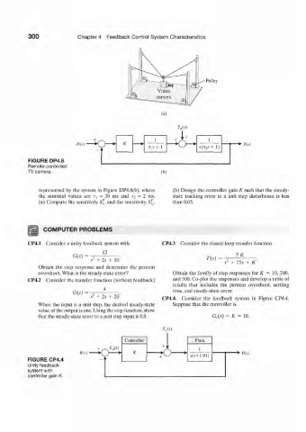
TAs)
A'(.v) *• « 5 )
FIGURE DP4.8
Remote-controlled
TV camera. (b)
represented by the system in Figure DP4.8(b). where (b) Design the controller gain K such that the steady-
the nominal values are T-^ = 20 ms and r 2 - 2 ms. state tracking error to a unit step disturbance is less
(a) Compute the sensitivity SZ and the sensitivity S„. than 0.05,
COMPUTER PROBLEMS
CP4.1 Consider a unity feedback system with CP4.3 Consider the closed-loop transfer function
G(s) = — . SK
s 2 + Zs + 10 Til) s 2 + 15s + K
Obtain the step response and determine the percent
overshoot. What is the steady-state error? Obtain the family of step responses for it = 10. 200,
CP4.2 Consider the transfer function (without feedback) and 500. Co-plot the responses and develop a table of
results that includes the percent overshoot, settling
4 time, and steady-state error.
s 1 + 2s + 20 CP4.4. Consider the feedback system in Figure CP4.4.
When the input is a unit step, the desired steady-state Suppose that the controller is
value of the output is one. Using the step function, show
that the steady-state error to a unit step input is 0.8. G,.(.?) = K = 10.
w
Controller Plant
+ ., 1
Rtt) * 0 — - * -fO .1(.1+ 1.91) -*• K(.v)
FIGURE CP4.4
Unity feedback
system with
controller gain K.