
Page 328 - Modern Control Systems
P. 328
302 Chapter 4 Feedback Control System Characteristics
A closed-loop control system for the system is shown
in Figure CP4.7(b). Suppose the desired angle
= 0°, k = 5,b = 0.9, nd/ = 1.
a
6 (t
(a) Determine the open-loop response 6(t) of the
system for a unit step disturbance (set r(t) = 0).
(b) With the controller gain K Q = 50, determine the
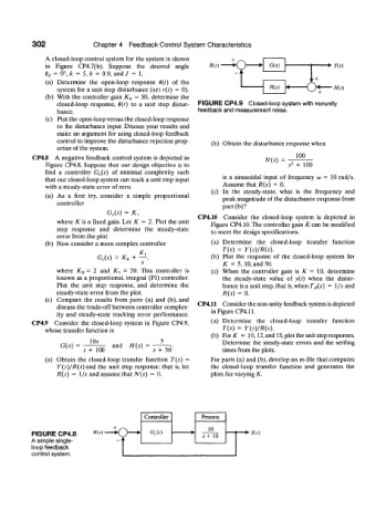
closed-loop response, 6(t) to a unit step distur- FIGURE CP4.9 Closed-loop system with nonunity
bance. feedback and measurement noise.
(c) Plot the open-loop versus the closed-loop response
to the disturbance input. Discuss your results and
make an argument for using closed-loop feedback
control to improve the disturbance rejection prop- (b) Obtain the disturbance response when
erties of the system.
CP4.8 A negative feedback control system is depicted in N(s) 100
Figure CP4.8. Suppose that our design objective is to s 2 + 100
find a controller G c(s) of minimal complexity such
that our closed-loop system can track a unit step input is a sinusoidal input of frequency a> = 10 rad/s.
with a steady-state error of zero. Assume that R(s) = 0.
(c) In the steady-state, what is the frequency and
(a) As a first try, consider a simple proportional peak magnitude of the disturbance response from
controller
part(b)?
G e(s) = K,
depicted
is
in
where K is a fixed gain. Let K = 2. Plot the unit CP4.10 Consider the closed-loop system can be modified
Figure
CP4.1().The controller gain K
step response and determine the steady-state to meet the design specifications.
error from the plot.
(b) Now consider a more complex controller (a) Determine the closed-loop transfer function
T(s) = Y(s)/R(s).
G c(s) = K {) + -±, (b) Plot the response of the closed-loop system for
K = 5,10, and 50.
where K Q = 2 and K^ - 20. This controller is (c) When the controller gain is K = 10, determine
known as a proportional, integral (PI) controller. the steady-state value of y{t) when the distur-
Plot the unit step response, and determine the bance is a unit step, that is, when T ti(s) = I/s and
steady-state error from the plot. R(s) = 0.
(c) Compare the results from parts (a) and (b). and CP4.11 Consider the non-unity feedback system is depicted
discuss the trade-off between controller complex- in Figure CP4.11.
ity and steady-state tracking error performance.
CP4.9 Consider the closed-loop system in Figure CP4.9, (a) Determine the closed-loop transfer function
whose transfer function is r(.v) = Y(s)/R(s).
(b) For AT = 10,12, and 15, plot the unit step responses.
10* 5 Determine the steady-state errors and the settling
G(.v) and H(s)
s + 100 .v + 50' times from the plots.
(a) Obtain the closed-loop transfer function T(s) = For parts (a) and (b), develop an m-file that computes
Y(s)/R(s) and the unit step response; that is, let the closed-loop transfer function and generates the
R(s) = l/.v and assume that N(s) = 0. plots for varying K.
Controller Process
10
FIGURE CP4.8 A'(.v) G c(s) s+ 10 • Y(s)
A simple single-
loop feedback
control system.