
Page 327 - Modern Control Systems
P. 327
Computer Problems 301
(a) Develop an m-file to compute the closed-loop value is used for design purposes only, since in reality
transfer function T(s) — Y(s)/R(s) and plot the unit the value is not precisely known. The objective of our
step response, (b) In the same m-file, compute the analysis is to investigate the sensitivity of the closed-
transfer function from the disturbance T,i(s) to the loop system to the parameter a.
output Y(s) and plot the unit step disturbance re-
sponse. (c) From the plots in (a) and (b) above, esti- (a) When a = 1, show analytically that the steady-
mate the steady-state tracking error to the unit step state value of y{t) is equal to 2 when r{t) is a unit
step. Verify that the unit step response is within
input and the steady-state tracking error to the unit
2% of the final value after 4 seconds.
step disturbance input, (d) From the plots in (a) and
(b) The sensitivity of the system to changes in the para-
(b) above, estimate the maximum tracking error to the
meter a can be investigated by studying the effects
unit step input and the maximum tracking error to the
of parameter changes on the transient response.
unit step disturbance input. At approximately what
times do the maximum errors occur? Plot the unit step response for a = 0.5,2, and 5.
Discuss the results.
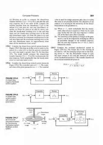
CP4.5 Consider the closed-loop control system shown in
Figure CP4.5. Develop an m-file script to assist in the CP4.7 Consider the torsional mechanical system in
search for a value of k so that the percent overshoot Figure CP4.7(a). The torque due to the twisting of
to a unit step input is greater than 1%, but less than the shaft is -k6; the damping torque due to the brak-
10%. The script should compute the closed-loop ing device is -bd; the disturbance torque is r rf(f);
transfer function T{s) = Y(s)/R(s) and generate the the input torque is r(t); and the moment of inertia
step response. Verify graphically that the steady-state of the mechanical system is /.The transfer function of
error to a unit step input is zero. the torsional mechanical system is
CP4.6 Consider the closed-loop control system shown in 1/7
Figure CP4.6. The controller gain is K =2. The nomi- GO) s 2 + (b/J)s + k/J
nal value of the plant parameter is a = 1. The nominal
Controller Process
10
FIGURE CP4.5 K(.v) • Q— s + k -*• Y(s)
A closed-loop
negative feedback
control system.
Controller Process
FIGURE CP4.6 K 1
A closed-loop «.v) • . s — a *• >'(.?)
control system
with uncertain
parameter a.
',! IS) Mechanical
tjit). Disturbance
system
torque
Controller
FIGURE CP4.7 + J • + 1/./
(a) A torsional > > *o * > , b k 9{s)
mechanical system. Braking
(b) The torsional r(i). Input device
mechanical system torque
feedback control
system. (a) (b)