
Page 323 - Modern Control Systems
P. 323
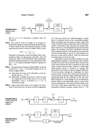
Design  Problems                                                    297
                                                    Load
                                                  disturbance
                                        Controller            G(s)
                         LO lt(s)
                        Desired  irv-*     K                   I           io(s)
       FIGURE DP4.1               X             —rA-*        s  + 4       Actual
       Speed  control    speed                                             speed
       system.                    I

           that  10  <  /C  <  25.  Determine  a  suitable  value  for  [17]. The  laser  allows  the  ophthalmologist  to  apply
           the gain  K.                                 heat  to a  location  in  the  eye  in a  controlled  manner.
                                                        Many procedures  use the retina  as a laser target. The
       DP4.2  The  control  of  the  roll  angle  of  an  airplane  is
           achieved  by using the torque developed  by the ailerons.   retina  is the thin sensory tissue that rests on  the  inner
           A  linear  model  of the  roll  control  system  for  a small   surface  of the back  of the  eye and  is the actual trans-
           experimental  aircraft  is shown  in Figure  DP4.2, where   ducer of the eye, converting light energy into electrical
                                                        pulses.  On  occasion,  this  layer  will  detach  from  the
                      G(.v)  =        .                 wall, resulting in death  of the detached area  from  lack
                              2
                             .v  +  45  +  9            of  blood  and  leading  to  partial  or  total  blindness  in
           The goal  is to maintain a small roll angle 6 due  to dis-  that eye. A  laser can be  used to "weld" the retina  into
           turbances.  Select  an  appropriate  gain  KK X  that  will  its proper place on the inner wall.
           reduce  the  effect  of  the  disturbance  while  attaining a   Automated  control  of  position  enables  the  oph-
           desirable transient response  to a step disturbance, with   thalmologist to indicate to the controller where lesions
           0 f/(/)  =  0. To obtain a desirable transient  response, let   should  be inserted. The  controller  then  monitors  the
           KK :  <  35.                                 retina  and  controls  the  laser's  position  so  that  each
       DP4.3  The speed control system of Figure DP4.1 is altered   lesion  is placed  at  the proper  location. A  wide-angle
           so  that  G(s)  =  l/(.v  +  5)  and  the  feedback  is K u  as  video-camera  system  is  required  to  monitor  the
           shown in Figure DP4.3.                       movement  of the retina, as shown  in Figure DP4.4(a).
                                                        If  the  eye  moves  during  the  irradiation,  the  laser
           (a)  Determine  the  range  of /(|  allowable so that  the  must  be either redirected  or turned  off. The  position-
              steady state  is e ss  ^  1 %.            control system is shown  in Figure DP4.4(b). Select an
           (b)  Determine  a suitable value  for  K^  and  K so  that  appropriate  gain  for  the  controller  so  that  the  tran-
              the magnitude  of the steady-state error  to a wind   sient  response  to  a step  change  in r{t)  is  satisfactory
              disturbance  T d{i)  -  2t mrad/s, 0  <  t  <  5 s,  is  and  the  effect  of  the  disturbance  due to  noise  in  the
              less than  0.1 mrad.                      system is minimized. Also, ensure that the steady-state
       DP4.4  Lasers  have  been  used  in  eye  surgery  for  more  error  for  a step  input  command  is  zero. To  ensure
           than 25 years. They can cut tissue or aid in coagulation   acceptable  transient  response, require  that  K  <  10.


                                                        TAs)


       FIGURE DP4.2                                                            0(s)
       Control of the roll                                                   Roll angle
       angle of an
       airplane.

                                                 TAs)
                                                  1        G(s)
                                         K                  1
                        IO.I(S)              -ti-    — •   s + 5
                                 k                                        Speed
       FIGURE DP4.3
       Speed  control
       system.                                    * i      Tachome ter