
Page 324 - Modern Control Systems
P. 324
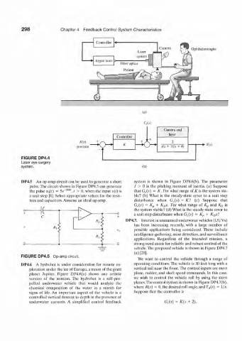
298              Chapter 4  Feedback  Control System  Characteristics

                                          Controller
                                                                     Camera        Ophthalmologist
                                                            Laser
                                          Argon  laser  Fiber optics  t!


                                  position                                             -•  Y(s)

          FIGURE DP4.4
          Laser eye surgery
          system.                                             (h)


          DP4.5  An op-amp circuit can be used to generate a short   system  is  shown  in  Figure  DP4.6(b). The  parameter
              pulse. The circuit  shown  in Figure DP4.5 can  generate  ./  >  0  is the  pitching  moment  of  inertia,  (a)  Suppose
                              10
              the pulse v n(t)  =  5e~ '", r  >  0, when the input  v{i) is   that  GJs)  =  K,  For what range  of if  is the system sta-
              a unit step  [6]. Select appropriate  values  for  the resis-  ble?  (b)  What  is the  steady-state  error  to  a  unit  step
              tors and capacitors. Assume an ideal op-amp.   disturbance  when  G (.(s)  =  Kl  (c)  Suppose  that
                                                           G t(s)  =  K p  +  Kj>s. For  what  range  of  K p  and  Ko  is
                  K                                        the system stable?  (d) What is the steady-slate error  to
                                                           a unit step disturbance when G c(s)
                                                                                            K 0s'l
                                                                                          +
                                                                                     =
                                                                                       K r
                                                       DP4.7.  Interest  in unmanned  underwater  vehicles (UUVs)
                                                           has  been  increasing  recently,  with  a  large  number  of
                                                           possible  applications  being  considered. These  include
                                                           intelligence-gathering, mine detection, and surveillance
                                                           applications.  Regardless  of  the  intended  mission,  a
                                                           strong need exists for reliable and robust control of the
                                                           vehicle. The proposed vehicle is shown  in Figure DP4.7
                                                           (a) [28].
          FIGURE DP4.5  Op-amp circuit.
                                                            We  want  to  control  the  vehicle  through  a range  of
          DP4.6  A  hydrobol  is under  consideration  for  remote  ex-  operating conditions. The  vehicle is 30 feet  long with a
              ploration  under the ice of Europa. a moon  of the giant   vertical sail near the front.The  control inputs are stern
              planet  Jupiter.  Figure  DP4.6(a)  shows  one  artistic  plane, rudder, and  shaft  speed  commands. In  this case,
              version  of  the  mission. The  hydrobot  is  a  self-pro-  we  wish  to  control  the  vehicle  roll  by  using  the  stern
              pelled  underwater  vehicle  that  would  analyze  the  planes. The control system is shown  in Figure DP4.7(b),
              chemical  composition  of  the  water  in  a  search  for  where R(x)  =  0, the desired roll angle, and T^s)  =  l/.v.
              signs  of  life.  An  important  aspect  of  the  vehicle  is a   Suppose that the controller  is
              controlled  vertical descent  lo depth  in the presence of
              underwater  currents.  A  simplified  control  feedback   G,.(s) =  K(s  +  2).