
Page 333 - Modern Control Systems
P. 333
Section 5.2 Test Input Signals 307
Gis)
Ks) ~«-0 » O >'(.v) /?(.v) G(s) "• Y(s)
0
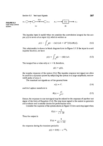
FIGURE 5.3
Open-loop control
system. (a) (b)
The impulse input is useful when we consider the convolution integral for the out-
put y(t) in terms of an input r(t), which is written as
f 1
y(0 g(t-r)r(r)dr = 5r {G(s)R(s)} (5.2)
This relationship is shown in block diagram form in Figure 5.3. If the input is a unit
impulse function, we have
v(0 -f g(t - T)8(T) dr. (5.3)
The integral has a value only at T = 0; therefore,
y(0 = g(0>
the impulse response of the system G(s). The impulse response test signal can often
be used for a dynamic system by subjecting the system to a large-amplitude, narrow-
width pulse of area A.
The standard test signals are of the general form
r{t) = t\ (5.4)
and the Laplace transform is
R(s) = (5.5)
n«+l'
Hence, the response to one test signal may be related to the response of another test
signal of the form of Equation (5.4). The step input signal is the easiest to generate
and evaluate and is usually chosen for performance tests.
Consider the response of the system shown in Figure 5.3 for a unit step input when
G(s) =
s + 10
Then the output is
9
Y(s) =
s(s + 10)'
the response during the transient period is
10
y(0 = 0.9(1 - e~ %