
Page 337 - Modern Control Systems
P. 337
Section 5.3 Performance of Second-Order Systems 311
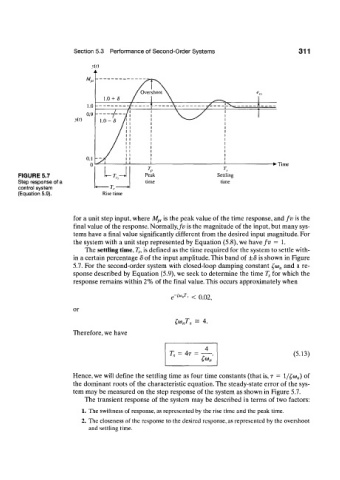
y(/)
><t)
• Time
FIGURE 5.7
Step response of a
control system
(Equation 5.9). Rise time
for a unit step input, where M p, is the peak value of the time response, and fv is the
final value of the response. Normally,fv is the magnitude of the input, but many sys-
tems have a final value significantly different from the desired input magnitude. For
the system with a unit step represented by Equation (5.8), we have fv = 1.
The settling time, T s, is defined as the time required for the system to settle with-
in a certain percentage 8 of the input amplitude. This band of ±8 is shown in Figure
5.7. For the second-order system with closed-loop damping constant £a) n and a re-
sponse described by Equation (5.9), we seek to determine the time T s for which the
response remains within 2% of the final value. This occurs approximately when
e-;o>,;i\ < 0 0 2 i
or
= 4.
£to nT s
Therefore, we have
= 4r = (5.13)
T r
£*»„'
Hence, we will define the settling time as four time constants (that is, T = l/£ot>„) of
the dominant roots of the characteristic equation. The steady-state error of the sys-
tem may be measured on the step response of the system as shown in Figure 5.7.
The transient response of the system may be described in terms of two factors:
1. The swiftness of response, as represented by the rise time and the peak time.
2. The closeness of the response to the desired response, as represented by the overshoot
and settling time.