
Page 339 - Modern Control Systems
P. 339
Section 5.3 Performance of Second-Order Systems 313
Table 5.2 Percent Peak Overshoot Versus Damping Ratio for a
Second-Order System
Damping ratio 0.9 0.8 0.7 0.6 0.5 0.4 0.3
Percent overshoot 0.2 1.5 4.6 9.5 16.3 25.4 37.2
the damping ratio. Again, we are confronted with a necessary compromise between
the swiftness of response and the allowable overshoot.
The swiftness of step response can be measured as the time it takes to rise from
10% to 90% of the magnitude of the step input. This is the definition of the rise time,
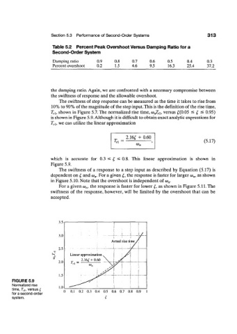
T rl, shown in Figure 5.7. The normalized rise time, (o nT ri, versus £(0.05 < I ^ 0.95)
is shown in Figure 5.9. Although it is difficult to obtain exact analytic expressions for
T rl, we can utilize the linear approximation
2.16£ + 0.60
= (5.17)
T n
(Or,
which is accurate for 0.3 < t, ^ 0.8. This linear approximation is shown in
Figure 5.9.
The swiftness of a response to a step input as described by Equation (5.17) is
dependent on t, and o) n. For a given £, the response is faster for larger w,„ as shown
in Figure 5.10. Note that the overshoot is independent of (o n.
For a given <o n, the response is faster for lower £, as shown in Figure 5.11. The
swiftness of the response, however, will be limited by the overshoot that can be
accepted.
.1.0 1
.
3.0 -I -U /
A ctual rise time /
/
2.5
•
Linear approximation .
_ 2.16^+0.60 . \ _
2.0
'' *>,, \
1 <r \
1.5
1 Zr' \
FIGURE 5.9
Normalized rise 1
time, T r1, versus f 1.0
for a second-order 0 0.1 0.2 0.3 0.4 0.5 0.6 0.7 0.8 0.9 1
system.