
Page 343 - Modern Control Systems
P. 343
Section 5.4 Effects of a Third Pole and a Zero on the Second-Order System Response 317
Table 5.4 The Response of a Second-Order
System with a Zero and £ = 0.45
Percent Settling Peak
a to
IC n Overshoot Time Time
5 23.1 8.0 3.0
2 39.7 7.6 2.2
1 89.9 10.1 1.8
0.5 210.0 10.3 1.5
Note:T\m& is normalized as o> nt, and settling time is based on a 2%
criterion.
The transient response of a system with one zero and two poles may be affected
by the location of the zero [5]. The percent overshoot for a step input as a function
of a/((o n, when £ := 1, is given in Figure 5.13(a) for the system transfer function
(a>l/a)(s + a)
T(s) =
2'
s + 2£(o ns + oof,
The actual transient response for a step input is shown in Figure 5.13(b) for selected
values of a/£(o„. The actual response for these selected values is summarized in
Table 5.4 when £ = 0.45.
The correlation of the time-domain response of a system with the s-plane loca-
tion of the poles of the closed-loop transfer function is very useful for selecting the
specifications of a system. To illustrate clearly the utility of the s-plane, let us consid-
er a simple example.
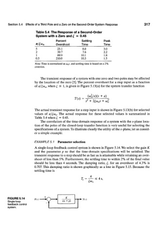
EXAMPLE 5.1 Parameter selection
A single-loop feedback control system is shown in Figure 5.14. We select the gain K
and the parameter p so that the time-domain specifications will be satisfied. The
transient response to a step should be as fast as is attainable while retaining an over-
shoot of less than 5%. Furthermore, the settling time to within 2% of the final value
should be less than 4 seconds. The damping ratio, £, for an overshoot of 4.3% is
0.707. This damping ratio is shown graphically as a line in Figure 5.15. Because the
settling time is
4
7; = — < 4 s ,
fan
FIGURE 5.14 A?(.v) }'(v)
Single-loop
feedback control
system.