
Page 336 - Modern Control Systems
P. 336
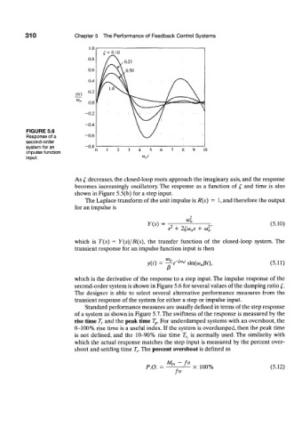
310


          FIGURE 5.6
          Response of a
          second-order
          system for an
          impulse function
          input.


                           As  £ decreases, the closed-loop roots approach the imaginary  axis, and  the  response
                           becomes  increasingly  oscillatory. The  response  as  a  function  of  £  and  time  is  also
                           shown  in Figure 5.5(b)  for  a step input.
                              The Laplace transform  of the unit impulse is R(s)  =  1, and therefore  the output
                           for  an impulse  is

                                                    Y(s)  =                                   (5.10)
                                                            2
                                                           .v  +  2£w„s  +  o)f t
                           which  is  T(s)  =  Y(s)/R(s),  the  transfer  function  of  the  closed-loop  system.  The
                           transient response for  an impulse function  input  is then

                                                          0)n  r  .
                                                    X0 =   je    sm.(a) n(3t),                (5.11)

                           which  is the derivative  of the  response to  a step input. The impulse  response  of  the
                           second-order system is shown in Figure  5.6 for several values of the damping ratio £.
                           The  designer  is  able  to  select  several  alternative  performance  measures  from  the
                           transient  response  of the system for either  a step or impulse  input.
                              Standard performance  measures are usually defined  in terms of the step response
                           of  a system  as shown in Figure 5.7. The swiftness  of the response  is measured  by  the
                           rise time T r and the peak time T p. For underdamped  systems with an overshoot, the
                           0-100%  rise time  is a useful  index. If the system  is overdamped, then the peak  time
                           is not  defined,  and  the  10-90%  rise  time  7 f|  is normally  used. The  similarity  with
                           which  the  actual response  matches  the  step input  is measured  by the percent  over-
                           shoot and settling time T s. The percent overshoot is defined  as


                                                                J
                                                   P.O.  =  '  r   X  100%                    (5.12)