Page 313 - Modern Control Systems
P. 313

Problems                                                             287
         PROBLEMS

        P4.1  The  open-loop  transfer  function  of  a fluid-flow  sys-  P4.2  It  is important  to ensure passenger comfort  on  ships
           tem can be written  as                        by stabilizing the  ship's  oscillations due  to waves [13].
                                                         Most  ship  stabilization  systems  use  fins  or  hydrofoils
                           AQ 2 (*)  =  1
                     G(s)  =                             projecting  into  the  water  to  generate  a  stabilization
                           AQi(s)  TS  +  V              torque  on  the  ship. A  simple  diagram  of  a ship  stabi-
           where  T =  RC,  Risa  constant equivalent to the resis-  lization  system  is  shown  in  Figure  P4.2. The  rolling
                                                 1/2
           tance  offered  by  the  orifice  so that  1/R  =  '/2&.tfo '  motion  of  a ship can be regarded  as an oscillating  pen-
           and  C  =  the  cross-sectional  area  of  the  tank.  Since  dulum  with  a deviation  from  the  vertical  of  $ degrees
           A / /  =  R  AQ 2,  we have the following  for the  transfer  and  a typical period  of 3 seconds. The transfer  function
           function  relating the head  to the input  change:  of  a typical ship is
                           M(s)      R                                         7
                    Gi(s)  =                                       G(s)
                          A £>,(*)  RCs  +  1'                           S 2  +  2((1),,5  +  (it),,
           For  a closed-loop  feedback  system,  a  float-level  sen-
                                                         where  &>„ =  3 rad/s  and  £  =  0.20.  With  this  low
           sor  and  valve  may  be  used  as  shown  in  Figure P4.1.
                                                         damping factor  £, the oscillations continue  for  sever-
           Assuming  the  float  is  a  negligible  mass, the  valve  is
                                                         al cycles, and  the  rolling amplitude  can reach  18°  for
           controlled  so that  a reduction in the flow rate, A(2i, is
                                                         the  expected  amplitude  of  waves  in  a  normal  sea.
           proportional  to  an  increase  in  head,  AH,  or
                                                        Determine  and  compare  the  open-loop  and  closed-
           A(?i  =  -KAH.  Draw  a  closed-loop  flow  graph  or
           block  diagram.  Determine  and  compare  the  open-  loop system for  (a) sensitivity to changes in the  actu-
           loop  and  closed-loop  systems  for  (a)  sensitivity  to  ator  constant  K„ and  the  roll sensor  K\,  and  (b)  the
                                                         ability  to  reduce  the  effects  of  step  disturbances  of
           changes  in  the  equivalent  coefficient  R  and  the  feed-
                                                        the  waves.  Note  that  the  desired  roll  d^s)  is  zero
           back  coefficient  K, (b) the ability  to reduce  the  effects
                                                         degrees.
           of  a  disturbance  in  the  level  AH(s),  and  (c)  the
           steady-state error  of the level (head) for  a step change   P4.3  One  of  the  most  important  variables  that  must  be
           of the  input  A<2,(.s).                     controlled  in industrial and chemical systems is temper-
                                                         ature. A simple representation  of a thermal control sys-
                                                         tem is shown  in Figure P4.3 [14].The temperature  2T of
                           d§b
                                                         the process  is controlled  by the heater with a resistance
                                                        R.  An  approximate  representation  of the  dynamic  lin-
                                                        early  relates  the  heat  loss  from  the  process  to  the
         0i  +  AG,       ^                             temperature  difference  9i  -  ST e . This relation  holds  if
                                   6                    the  energy  storage difference  is  relatively vessel  walls
                                                            temperature
                                                                                        small
                                                                                             and
                                                         the
                                                                         the heater
                                                                                 and
                                                                       of
                                                                                    the
                                H         Q 2  + A0,     is  negligible. Also,  it  is  assumed  that  the  voltage  e /(
                                                        applied  to  the  heater  is  proportional  to  e^ired  o r
                                               •
                                                           =    =  k aE be(t),  where  is the constant  of  the
                                                        e h  kE b             k a
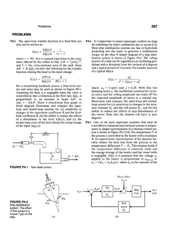
       FIGURE P4.1  Tank level control.
                                                                        Wave  effect
                                                      +    E a(s)
                                                ffjU)  — K 3
       FIGURE  P4.2
       Ship stabilization
       system. The effect
       of the waves is a
       torque T d(s) on the
       ship.                     (a)                                   (b)
   308   309   310   311   312   313   314   315   316   317   318