
Page 355 - Modern Control Systems
P. 355
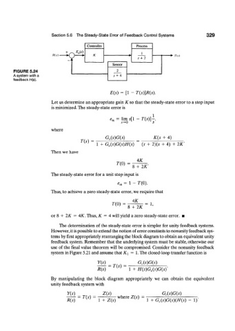
Section 5.6  The Steady-State  Error of Feedback Control  Systems   329

                                        Controller           Process
                                 -v  E u(s)                     I
                        /f(.y)            K                                 •  Yis)
                                                              5 +  2
                                 k
                                                   Sensor
       FIGURE 5.24                                   2
       A system with a                             5 +  4
       feedback H(s).

                                                  E(s)  =  [1 -  T(s)]R(s).

                        Let us determine an appropriate gain K so that the steady-state error to a step input
                        is minimized. The steady-state error is

                                                                     1
                                                     =  lim s[l  —  T(s)]—,
                                                   s                J
                                                  e ss s
                                                       5^0          5
                        where
                                                G c(s)G(s)           K(s  +  4)
                                     T(s)  =
                                            1  +  G c(s)G(s)H(s)  (s  +  2)(5  +  4)  +  2K'
                        Then we have
                                                              4K
                                                     T(0)  =
                                                            8  + 2K
                        The steady-state error for a unit step input is
                                                     *„  =  1 -  7-(0).
                        Thus, to achieve a zero steady-state error, we require that

                                                            4K
                                                   7-(0)         =  1,
                                                          8  + 2K
                        or 8 +  2K  = 4K. Thus, K  = 4 will yield a zero steady-state error.  •

                           The determination  of the steady-state error is simpler for  unity feedback  systems.
                        However, it is possible to extend the notion of error constants to nonunity feedback sys-
                        tems by first appropriately rearranging the block diagram to obtain an equivalent unity
                        feedback  system. Remember that the underlying system must be stable, otherwise our
                        use  of the final  value theorem  will be compromised. Consider  the nonunity  feedback
                        system in Figure 5.21  and assume that ^  =  1. The closed-loop transfer function is

                                            Y(s)              G c(s)G(s)
                                                 =  T(s)  =
                                            R(s)          1  +  H(s)G c(s)G(sY
                        By  manipulating  the  block  diagram  appropriately  we  can  obtain  the  equivalent
                        unity feedback  system with

                               Y(s)            Z(s)                      G c(s)G(s)
                                    =  T(s)          where Z(s)  =
                               R(s)          1  +  Z(s)           1  +  G c(s)G(s)(H(s)  -  1)'