
Page 57 - Modern Control Systems
P. 57
Section 1.9 Design Examples 31
Battery Speed
Tachometer
(a)
Controller Actuator Process
Desired
+ ^ Error ^ DC Rotating Actual
speed • Amplifier
motor disk speed
(voltage) i
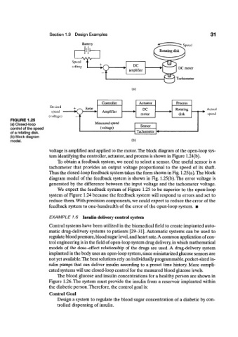
FIGURE 1.25
(a) Closed-loop Sensor
control of the speed (voltage)
of a rotating disk. Tachometer
(b) Block diagram
model. (b)
voltage is amplified and applied to the motor. The block diagram of the open-loop sys-
tem identifying the controller, actuator, and process is shown in Figure 1.24(b).
To obtain a feedback system, we need to select a sensor. One useful sensor is a
tachometer that provides an output voltage proportional to the speed of its shaft.
Thus the closed-loop feedback system takes the form shown in Fig. 1.25(a). The block
diagram model of the feedback system is shown in Fig. 1.25(b). The error voltage is
generated by the difference between the input voltage and the tachometer voltage.
We expect the feedback system of Figure 1.25 to be superior to the open-loop
system of Figure 1.24 because the feedback system will respond to errors and act to
reduce them. With precision components, we could expect to reduce the error of the
feedback system to one-hundredth of the error of the open-loop system. •
EXAMPLE 1.6 Insulin delivery control system
Control systems have been utilized in the biomedical field to create implanted auto-
matic drug-delivery systems to patients [29-31], Automatic systems can be used to
regulate blood pressure, blood sugar level, and heart rate, A common application of con-
trol engineering is in the field of open-loop system drug delivery, in which mathematical
models of the dose-effect relationship of the drugs are used. A drug-delivery system
implanted in the body uses an open-loop system, since miniaturized glucose sensors are
not yet available.The best solutions rely on individually programmable, pocket-sized in-
sulin pumps that can deliver insulin according to a preset time history. More compli-
cated systems will use closed-loop control for the measured blood glucose levels.
The blood glucose and insulin concentrations for a healthy person are shown in
Figure 1.26. The system must provide the insulin from a reservoir implanted within
the diabetic person. Therefore, the control goal is:
Control Goal
Design a system to regulate the blood sugar concentration of a diabetic by con-
trolled dispensing of insulin.