
Page 58 - Modern Control Systems
P. 58
32 Chapter 1 Introduction to Control Systems
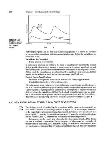
FIGURE 1.26
The blood glucose
and insulin levels Breakfast Dinner
for a healthy
person.
Referring to Figure 1.26, the next step in the design process is to define the variable
to be controlled. Associated with the control goal we can define the variable to be
controlled to be:
Variable to Be Controlled
Blood glucose concentration
In subsequent chapters, we will have the tools to quantitatively describe the control
design specifications using a variety of steady-state performance specifications and
transient response specifications, both in the time-domain and in the frequency domain.
At this point, the control design specifications will be qualitative and imprecise. In that
regard, for the problem at hand, we can state the design specification as:
Control Design Specifications
Provide a blood glucose level for the diabetic that closely approximates
(tracks) the glucose level of a healthy person.
Given the design goals, variables to be controlled, and control design specifications, we
can now propose a preliminary system configuration. An open-loop system would use
a preprogrammed signal generator and miniature motor pump to regulate the insulin
delivery rate as shown in Figure 1.27(a). The feedback control system would use a sen-
sor to measure the actual glucose level and compare that level with the desired level,
thus turning the motor pump on when it is required, as shown in Figure 1.27(b). •
1.10 SEQUENTIAL DESIGN EXAMPLE: DISK DRIVE READ SYSTEM
This design example, identified by the arrow icon, will be considered sequentially in
each chapter. We will use the design process of Figure 1.17 in each chapter to identi-
fy the steps that we are accomplishing. For example, in Chapter 1 we (1) identify the
control goal, (2) identify the variables to control, (3) write the initial specifications
for the variables, and (4) establish the preliminary system configuration.
Information can be readily and efficiently stored on magnetic disks. Disk drives
are used in notebook computers and larger computers of all sizes and are essentially all
standardized as defined by ANSI standards [50,63]. The worldwide total available mar-
ket for disk drives is greater than 650 million units [51]. In the past, disk drive designers