
Page 60 - Modern Control Systems
P. 60
34 Chapter 1 Introduction to Control Systems
Rotation
Spindle
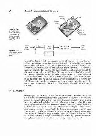
FIGURE 1.29
(a) A disk drive Track a
© 1999 Quantum Track b
Corporation. All Head slider
rights reserved.
(b) Diagram of a
disk drive. (a) (b)
Desired -. Error Actual
\r Control Actuator motor head
A ) * device and read arm
position position
FIGURE 1.30
Closed-loop control
system for disk Sensor
drive.
areas of "intelligence" under investigation include off-line error recovery, disk drive
failure warnings, and storing data across multiple disk drives. Consider the basic dia-
gram of a disk drive shown in Fig. 1.29.The goal of the disk drive reader device is to po-
sition the reader head to read the data stored on a track on the disk. The variable to
accurately control is the position of the reader head (mounted on a slider device).The
disk rotates at a speed between 1800 and 7200 rpm, and the head "flies" above the disk
at a distance of less than 100 nm. The initial specification for the position accuracy is
1 /xm. Furthermore, we plan to be able to move the head from track a to track b within
50 ms, if possible. Thus, we establish an initial system configuration as shown in Figure
1.30. This proposed closed-loop system uses a motor to actuate (move) the arm to the
desired location on the disk. We will consider the design of the disk drive further in
Chapter 2.
1.11 SUMMARY
In this chapter, we discussed open- and closed-loop feedback control systems. Exam-
ples of control systems through the course of history were presented to motivate and
connect the subject to the past. In terms of contemporary issues, key areas of appli-
cation were discussed, including htimanoid robots, unmanned aerial vehicles, wind
energy, hybrid automobiles, and embedded control. The central role of controls in
mechatronics was discussed. Mechatronics is the synergistic integration of mechanical,
electrical, and computer systems. Finally, the design process was presented in a struc-
tured form and included the following steps: the establishment of goals and variables
to be controlled, definition of specifications, system definition, modeling, and analy-
sis. The iterative nature of design allows us to handle the design gap effectively while
accomplishing necessary trade-offs in complexity, performance, and cost.