
Page 56 - Modern Control Systems
P. 56
3 0 Chapter 1 Introduction to Control Systems
Transmission of power is called power flow and the improved control of power
will increase its security and efficiency. Transmission lines have inductive, capacitive,
and resistive effects that result in dynamic impacts or disturbances. The smart grid
must anticipate and respond to system disturbances rapidly. This is referred to as
self-healing. In other words, a smart grid should be capable of managing significant
disturbances occurring on very short time scales. To accomplish this, the self-healing
process is constructed around the idea of a feedback control system where self-as-
sessments are used to detect and analyze disturbances so that corrective action can
be applied to restore the grid. This requires sensing and measurements to provide
information to the control systems. One of the benefits of using smart grids is that
renewable energy sources that depend on intermittent natural phenomena (such as
wind and sunshine) can potentially be utilized more efficiently by allowing for load
shedding when the wind dies out or clouds block the sunshine.
Feedback control systems will play an increasingly important role in the
development of smart grids as we move to the target date. It may be interesting to
recall the various topics discussed in this section in the context of control systems as
each chapter in this textbook unfolds new methods of control system design and
analysis.
EXAMPLE 1.5 Rotating disk speed control
Many modern devices employ a rotating disk held at a constant speed. For example,
a CD player requires a constant speed of rotation in spite of motor wear and varia-
tion and other component changes. Our goal is to design a system for rotating disk
speed control that will ensure that the actual speed of rotation is within a specified
percentage of the desired speed [40,43]. We will consider a system without feedback
and a system with feedback.
To obtain disk rotation, we will select a DC motor as the actuator because it
provides a speed proportional to the applied motor voltage. For the input voltage to
the motor, we will select an amplifier that can provide the required power.
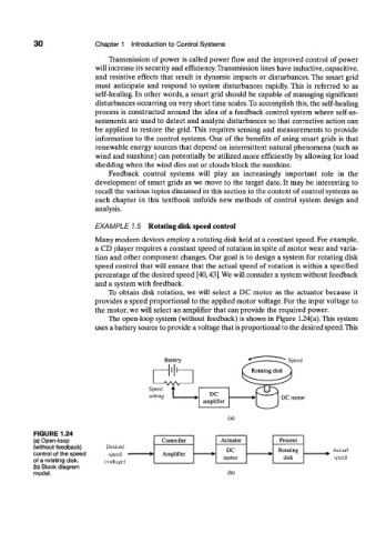
The open-loop system (without feedback) is shown in Figure 1.24(a). This system
uses a battery source to provide a voltage that is proportional to the desired speed. This
Battery
-llll-
Speed •
setting I p
(a)
FIGURE 1.24
(a) Open-loop Controller Actuator Process
(without feedback)
DC Rotating
control of the speed Amplifier
motor disk
of a rotating disk.
(b) Block diagram
model. (b)