
Page 210 - Modern Control of DC-Based Power Systems
P. 210
174 Modern Control of DC-Based Power Systems
negative definite, has as a consequence for the error system that it is glob-
ally asymptotical stable around the origin.
5.5.4 Simulation Results
5.5.4.1 Cascaded System
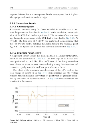
A cascaded converter setup has been modeled in Matlab-SIMULINK
with the parameters described in Table 6.1. In the simulation, a step vari-
ation of the CPL load has been performed. The variation of the bus volt-
age during the step change of the CPL load is described in Fig. 5.43.At
t 5 0.25 s the load step of 7.5 MW was performed, demonstrating that
the Virt Dist BS control stabilizes the system towards the reference point
V ref 5 1: The dynamic of the inductor current is described in Fig. 5.44.
5.5.4.2 Shipboard Power System
A Shipboard Power System has been modeled in Matlab\SIMULINK,
based on the parameters in Table 6.2. The load steps of 22.5 MW have
been performed at t 5 0.25 s. The coefficients of the droop controllers
were chosen to obtain an even current sharing among the converters. All
converters equally share the total load power between them.
The effect of the increasing and decreasing of the CPL load on the
load voltage is described in Fig. 5.45, demonstrating that the voltage
remains stable and reaches the voltage set-points that are gradually modi-
fied by the action of the droop control. In Fig. 5.46 one can observe the
transient for the current.
Figure 5.43 Voltage virtual distribution BS cascaded Ideal CPL Step 10.3 -
17.8 MW.