
Page 205 - Modern Control of DC-Based Power Systems
P. 205
Control Approaches for Parallel Source Converter Systems 169
u z Ẋ x 1
+ ʃ h (x ) + 1 ʃ
1
–
.
α (x )
1
f (x ) + h (x )α (x )
1 1 1
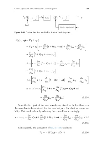
Figure 5.40 Control function αshifted in front of the integrator.
_ V 2 x 1 ; x 2 Þ 5 _ V 1 1 z 2 _z 2
ð
" #
@α @α
̈
5 _ V 1 1 z 2 u 2 @α f 1 hz 2 1 αÞ 1 _ y 1 y ref
ref
ð
@x 1 @y ref @_y
ref
h i
@V 1
5 f 1 hz 2 1 αÞ 2 _y
ref
ð
@z 1
" #
@α @α
1z 2 u 2 @α f 1 hz 2 1 αÞ 1 _ y 1 ̈
ref y ref
ð
@x 1 @y ref @_y ref
h i
@V 1
5 f 1 hz 2 1 αÞ 2 _y
ref
ð
@x 1
" #
@α @α
@V 1 @α
̈
1z 2 h 1 u 2 f 1 hz 2 1 αÞ 2 _ y 2 y ref
ref
ð
@z 1 @x 1 @y ref @_y ref
"
@V 1 @α
# Wz 1 1 z 2 h 1 u 2 fx 1 1 hz 2 1 αÞ
ð
ðÞ
ðÞ
@z 1 @x 1
@α @α
̈
2 _ y ref 2 y ref (5.154)
@y ref @_y ref
Since the first part of the sum was already stated to be less than zero,
the same has to be achieved for the two last parts (in blue) to ensure sta-
bility. This can be done by selecting the control law accordingly:
@V @α @α @α
u 52 cz 2 2 hx 1 1 f 1 hz 2 1 αÞ 2 _ y 2 ÿ ref ; c . 0
ref
ðÞ
ð
@z 1 @x 1 @y ref @_y ref
(5.155)
Consequently, the derivative of Eq. (5.153) results in:
_
2
V 2 52 Wðz 1 Þ 2 cz , 0 (5.156)
2