
Page 207 - Modern Control of DC-Based Power Systems
P. 207
Control Approaches for Parallel Source Converter Systems 171
R f L f I L PCC
d·E C f V R L I d
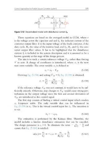
Figure 5.42 Decentralized model with disturbance current I d .
Those equations are based on the averaged model in CCM, where v
is the voltage across the capacitor and and I L the inductor current of the
converter output filter. E is the input voltage of the buck converter, d the
duty cycle, R L the value of the resistive load, and L f , R f , and C f the con-
verter output filter values. It has to be highlighted that the disturbance
current I d is included in the system description and it is assumed to be a
known quantity at this stage of the design process.
The aim is to track a certain reference voltage V ref rather than forcing
V to zero. A change of coordinates is introduced, where z 1 is the new
state error variable: The error variable z 1 is defined as:
(5.158)
z 1 5 x 1 2 V ref
Deriving Eq. (5.158) and setting _ V ref 5 0, Eq. (5.159) is obtained:
x 2 x 1 i d
_ z 1 5 2 2 (5.159)
C f R L C f C f
If the reference voltage V ref was not constant, it would have to be suf-
ficiently smooth. Otherwise, step changes in V ref would cause strong per-
turbations in the output voltage since the first and second derivatives of
V ref are introduced in the control signal.
The first step consists of finding a virtual control input which renders
z 1 Lyapunov stable. The only variable that can be influenced in
Eq. (5.159) is x 2 . This is the virtual control input for _z 1 . The intention is
to set:
_ z 1 52 c 1 z 1 (5.160)
The estimation is performed by the Kalman filter. Therefore, the
model includes a known disturbance estimation that can be canceled.
The design parameter is c 1 . 0. To eliminate the term 2 x 1 2 I d and
R L C f C f
ensure that Eq. (5.160) is satisfied:
x 2 x 1 I d
α x 1 5 52 c 1 z 1 1 1 (5.161)
ðÞ
C f R L C f C f