
Page 232 - Modern Control of DC-Based Power Systems
P. 232
196 Modern Control of DC-Based Power Systems
Bode diagram
20
Magnitude (dB) –20 0
–40
R R
W Wu u
–60
90
Phase (deg) –90 0
–180
10 –1 10 0 10 1 10 2 10 3 10 4 10 5
Frequency (Hz)
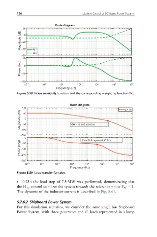
Figure 5.58 Noise sensitivity function and the corresponding weighting function W u .
Bode diagram
100 L = GK
Magnitude (dB) –50 0 GM = 19.8 dB at 242 Hz
50
–100
–150
0 PM = 68.8 degrees at 46.6 Hz
Phase (deg) –180
–90
–270
–360
10 –3 10 –2 10 –1 10 0 10 1 10 2 10 3 10 4
Frequency (Hz)
Figure 5.59 Loop transfer function.
t 5 0.25 s the load step of 7.5 MW was performed, demonstrating that
the H N control stabilizes the system towards the reference point V ref 5 1:
The dynamic of the inductor current is described in Fig. 5.61.
5.7.6.2 Shipboard Power System
For this simulation scenarios, we consider the same single bus Shipboard
Power System, with three generators and all loads represented in a lump