
Page 397 - Multidimensional Chromatography
P. 397
Multidimensional Chromatographic Applications in the Oil Industry 389
14.3.1 THE ANALYSIS OF BENZENE, TOLUENE AND HIGHER
AROMATICS IN LOW-BOILING FRACTIONS
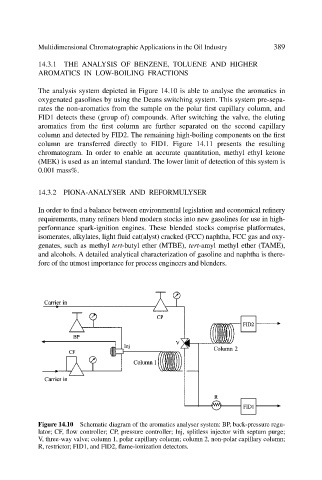
The analysis system depicted in Figure 14.10 is able to analyse the aromatics in
oxygenated gasolines by using the Deans switching system. This system pre-sepa-
rates the non-aromatics from the sample on the polar first capillary column, and
FID1 detects these (group of) compounds. After switching the valve, the eluting
aromatics from the first column are further separated on the second capillary
column and detected by FID2. The remaining high-boiling components on the first
column are transferred directly to FID1. Figure 14.11 presents the resulting
chromatogram. In order to enable an accurate quantitation, methyl ethyl ketone
(MEK) is used as an internal standard. The lower limit of detection of this system is
0.001 mass%.
14.3.2 PIONA-ANALYSER AND REFORMULYSER
In order to find a balance between environmental legislation and economical refinery
requirements, many refiners blend modern stocks into new gasolines for use in high-
performance spark-ignition engines. These blended stocks comprise platformates,
isomerates, alkylates, light fluid cat(alyst) cracked (FCC) naphtha, FCC gas and oxy-
genates, such as methyl tert-butyl ether (MTBE), tert-amyl methyl ether (TAME),
and alcohols. A detailed analytical characterization of gasoline and naphtha is there-
fore of the utmost importance for process engineers and blenders.
Figure 14.10 Schematic diagram of the aromatics analyser system: BP, back-pressure regu-
lator; CF, flow controller; CP, pressure controller; Inj, splitless injector with septum purge;
V, three-way valve; column 1, polar capillary column; column 2, non-polar capillary column;
R, restrictor; FID1, and FID2, flame-ionization detectors.