
Page 399 - Multidimensional Chromatography
P. 399
Multidimensional Chromatographic Applications in the Oil Industry 391
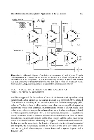
Figure 14.12 Schematic diagram of the Reformulyser system: Inj, split injector; C1, polar
capillary column; C2, packed column to retain the alcohols; C3, packed Porapak column for
the separation of the oxygenates; C4, non-polar capillary column; C5, packed 13X column;
A/E trap, Tenax trap to retain the aromatics; Olf. trap, trap to retain the olefins; Pt, olefins
hydrogenator; A trap, trap to retain the n-alkanes; FID, flame-ionization detector.
14.3.3 A DUAL SFC SYSTEM FOR THE ANALYSIS OF
TOTAL OLEFINS IN GASOLINES
A different approach for the analysis of the total olefin content of a gasoline, using
supercritical carbon dioxide as the carrier, is given in a proposed ASTM method.
This utilizes the switching of two packed supercritical fluid chromatography (SFC)
columns. The first column is a high-surface-area silica column, capable of separating
alkanes and olefins from aromatics, while the second column is a silver-loaded silica
column or a cation-exchange column in the silver form. A schematic diagram of such
a system is presented in Figure 14.14. In this technique, the sample is injected onto
the silica column, which is in series with the silver-loaded column. After elution of
the saturates, the aromatics remain on the silica column and the olefins have moved
to the silver-loaded column, where they are trapped. The silica column is then back-
flushed to elute the aromatics to the detector. After switching the silica column out of
the flowpath, the silver-loaded column is back-flushed to elute the olefins to the
detector. A typical chromatogram obtained from such a system is presented in
Figure 14.15.