
Page 395 - Multidimensional Chromatography
P. 395
Multidimensional Chromatographic Applications in the Oil Industry 387
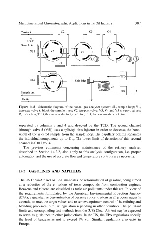
Figure 14.8 Schematic diagram of the natural gas analyser system: SL, sample loop; V1,
two-way valve to block the sample lines; V2, ten-port valve; V3, V4 and V5, six-port valves;
R, restriction; TCD, thermal-conductivity detector; FID, flame-ionization detector.
separated by columns 3 and 4 and detected by the TCD. The second channel
(through valve 5 (V5)) uses a split/splitless injector in order to decrease the band-
width of the injected sample from the sample loop. The capillary column separates
the individual components up to C 10 . The lower limit of detection of this second
channel is 0.001 vol%.
The previous comments concerning maintenance of the refinery analyser
described in Section 14.2.2, also apply to this analysis configuration, i.e. proper
automation and the use of accurate flow and temperature controls are a necessity.
14.3 GASOLINES AND NAPHTHAS
The US Clean Air Act of 1990 mandates the reformulation of gasoline, being aimed
at a reduction of the emissions of toxic compounds from combustion engines.
Benzene and toluene are classified as toxic air pollutants under this act. In view of
the requirements formulated by the American Environmental Protection Agency
(EPA), a quantitative determination of benzene concentrations at all process stages is
essential to meet the target values and to achieve optimum control of the refining and
blending processes. Similar legislation is pending in other countries. The pollutant
limits and corresponding test methods from the (US) Clean Air Act may be expected
to serve as guidelines in other jurisdictions. In the US, the EPA regulations specify
the level of benzene as not to exceed 1% vol. Similar regulations also exist in
Europe.