
Page 398 - Multidimensional Chromatography
P. 398
390 Multidimensional Chromatography
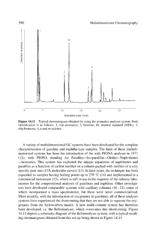
Figure 14.11 Typical chromatogram obtained by using the aromatics analyser system. Peak
identification is as follows: 1, non-aromatics; 2, benzene; IS, internal standard (MEK); 3,
ethylbenzene; 4, p-and m-xylenes.
A variety of multidimensional GC systems have been developed for the complete
characterization of gasoline and naphtha-type samples. The limit of these multidi-
mensional systems has been the introduction of the with PIONA-analyser in 1971
(12), with PIONA standing for Paraffins–Iso-paraffins–Olefins–Naph-thenes
–Aromatics. This system has exploited the unique separation of naphthenes and
paraffins as a function of carbon number on a column packed with zeolites of a very
specific pore size (13 molecular sieves) (13). In later years, the technique has been
expanded to samples having boiling points up to 270 °C (14) and implemented in a
commercial instrument (15), which is still in use in the majority of the refinery labo-
ratories for the compositional analyses of gasolines and naphthas. Other investiga-
tors have developed comparable systems with capillary columns (16–22), some of
which incorporated a mass spectrometer, but these were never commercialized.
More recently, with the introduction of oxygenates in gasolines, all of these analyser
systems have experienced the shortcoming that they are not able to separate the oxy-
genates from the hydrocarbon matrix. A new multi-column system has therefore
been developed, i.e. the Reformulyser, which overcomes this shortcoming. Figure
14.12 depicts a schematic diagram of the Reformulyser system, with a typical result-
ing chromatogram obtained from this set-up being shown in Figure 14.13.