
Page 194 - Multifunctional Photocatalytic Materials for Energy
P. 194
180 Multifunctional Photocatalytic Materials for Energy
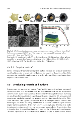
Fig. 8.21 (A) Schematic diagram showing amorphous sphere shapes evolving to hierarchical
hollow sphere shapes. (B) SEM and TEM images of the as-prepared hierarchical hollow
spheres. (C) I-V curves of the DSSCs.
Reprinted with permission from D. Wu et al., Monodisperse TiO 2 hierarchical hollow spheres
assembled by nanospindles for dye-sensitized solar cells. J. Mater. Chem. 22 (2012) 11665–
11671. Copyright 2012, The Royal Society of Chemistry Publications.
8.4.3.5 Template method
In this strategy, polymer spheres or porous carbon materials are normally utilized as
sacrificial templates to construct the HMSs. After growth or deposition of the TiO 2
precursor, the sacrificial templates are removed by solvent etching or calcination, leav-
ing well-constructed HMSs.
8.5 Concluding remarks and outlook
In this chapter, we reviewed two groups of metal oxide-based semiconductor layers used
in thin-film solar cells. We summarized the fabrication methods for the metal-based
semiconductor layers used to prepare efficient nanostructured photoanodes, including
sol-gel, hydrothermal, chemical deposition, and anodic oxidation. We also addressed
three typical interfacial materials and mesoporous layers for solar cells, including TiO 2 ,
ZnO, and SnO 2 . The applications of these nanostructured photoanode materials and
their impact on device efficiency and the role of different interfacial layers used in
improving the output of the device were reviewed. Although great effort has been made
to optimize the structure of the metal oxide-based semiconductor layers in thin-film
solar cells, three factors still need to be addressed: (a) the thickness and porosity of the
“scaffold” layer should be further increased for DSSCs/QDSCs, (b) the surface area of