
Page 125 - Book Hosokawa Nanoparticle Technology Handbook
P. 125
2.5 PORE STRUCTURE FUNDAMENTALS
Acid treatment
Sol gel reaction Acid treatment
n
o
r
C
o
o
f
Silica Coating Dissolution of Core e
s
i
s
l
o
i
Silica Coating
t
D
u
r
e
Core particle e
C
o
p
i
c
l
a
r
t
Core-Shell type
Silica hollow particle
(Calcium Carbonate) particle S i l i c a h o l l o w p a r t i cle
(Calcium Carbonate)
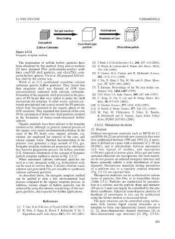
Figure 2.5.12
Inorganic template method.
The preparation of sulfide hollow particles have [3] J. Park: J. Colloid Interface Sci., 266, 107–114 (2003).
been attempted by this method. Song and co-workers [4] D. Walsh, B. Lebeau and S. Mann: Adv. Mater., 11(4),
[9] have prepared PSA (poly(styrene-acrylic) acid) 324–328 (1999).
latex core/CdS shell particles, and silica/TiO com- [5] F. Caruso, R.A. Caruso and H. Mohwald: Science,
2
posite hollow spheres. Yin et al. [6] prepared ZnS hol- 282, 1111–1114 (1998).
low shell by the similar way. [6] J. Yin, X. Qian, J. Yin, M. Shi and G. Zhou: Mater.
Walsh et al. [11] synthesized crystalline calcium
carbonate porous hollow particles. They found that Lett., 57, 3859–3863 (2003).
thin aragonite shell was formed in O/W type [7] T. Enomae: Proceedings of the 5th Asia textile con-
microemulsion saturated with calcium carbonate. ference, Vols. 1464–1467 (1999).
Formation of the aragonite shell proceeded in the pres- [8] O.D. Velev, T.A. Jade: Nature, 389, 447–448 (1997).
ence of PS beads that were added to make the shell [9] C. Song, G. Gu, Y. Lin and H. Wang: Mater. Res.
incorporate the template. In other words, calcium car- Bull., 38, 917–924 (2003).
bonate precipitated and coated around the PS particles [10] G. Decher: Science, 277, 1232–1234 (1997).
which were incorporated in the organic phase of the [11] D. Walsh, S. Mann: Nature, 377, 320–323, (1995).
O/W emulsion. They reported that removal of the core [12] M. Fuji, M. Chikazawa, T. Takei, K. Tanabe,
PS by calcination of dried core–shell particles resulted K. Mitsuhashi and N. Tagami, Japan Kokai Tokkyo
in the formation of honey-comb-structured hollow Koho, JP2005-263550A (2005).
spheres.
Organic materials have been utilized in the template 2.5.2.2. Mesoporous structures
method so far, although, in general, removal process of
the organic core causes environmental pollution. In the (1) Structure
cases of the PS beads core, organic solvents, e.g. Ordered mesoporous materials such as MCM-41 [1]
toluene, are employed for removal of the core, and and FSM-16 [2] are relatively new materials that were
release organic waste. Thermal decomposition of the first synthesized between 1990 and 1992 [3]. A meso-
polymer core generates a large amount of CO gas. pore is defined as a pore with a diameter of 2–50 nm
2
Inorganic template methods are proposed as alternative (IUPAC), and is intermediate between micropores
less harmful preparation process for hollow particles ( 2 nm) typical of zeolites, and macropores
[12]. Schematic illustration of the concept of inorganic ( 50 nm) typical of porous glass. Silica gel and some
particle template method is shown in Fig. 2.5.12. activated charcoals are mesoporous, but such materi-
When nanosized calcium carbonate particles are als do not possess an ordered mesopore structure and
used as a core, inorganic acids, e.g. hydrochloric acid, hence generally exhibit a wide distribution of pore
can be used to remove them. Calcium chloride waste diameter. Mesoporous materials having mesopores
solution and generated CO are reusable to synthesize of a uniform size in a regularly ordered structure
2
calcium carbonate particles. (Fig. 2.5.13) are reported here.
As described above, the inorganic template method Mesoporous materials can be synthesized in various
can be applied to plan a less environmental load forms as particles, thin film, or as monolithic blocks
process compared to the organic template process. In (Table 2.5.1). Particles are synthesized by precipita-
addition, various shapes of hollow particles can be tion in a solvent, and the particle shape and diameter
achieved by using the intrinsic morphology of the inor- (10 nm to 1 mm) can largely be controlled by the syn-
ganic particles, and expected for further applications. thesis conditions. Spherical monodisperse particles of
hundreds of nanometers in size can be synthesized
using the Stöber method as discussed below.
References The pore structure can be controlled using surfac-
tants with various liquid crystal structures as a
[1] T. Tani: R & D Review of Toyota CRDI, 34(3) (1999). template to form one-dimensional tunnel structures
[2] H. Toda, S. Kaga, K. Hosoi, T. Kobayashi, Y. Ito, T. [1, 2], three-dimensional channel structures [1], or
Higashihara and T. Aida: Zairyo, 50(5), 474–481 (2001). three-dimensional cage structures [4] (Fig. 2.5.14).
101