
Page 382 - Book Hosokawa Nanoparticle Technology Handbook
P. 382
FUNDAMENTALS CH. 6 EVALUATION METHODS FOR PROPERTIES OF NANOSTRUCTURED BODY
(1) Measurements for bulk thermoelectric materials is little chance of having chemical reaction between
(including bulk materials with micro-/nanostructures) the sample and the paste at the low temperature, reli-
able contacts can be made by the pastes. In Fig. 6.4.16d
Seebeck coefficient is defined as the ratio of electro-
motive force V emf to temperature difference T and the fine copper pieces attached to the sample are used
can be expressed as below. as pick-up-leads for both temperature and voltage.
Harman method [3] is a unique method to deter-
mine thermoelectric Figure of Merit, Z, directly
V V
S emf emf (6.4.12) using the Peltier effect of test samples. Applying
T T T L external current source to the sample adiabatically,
H
the temperature gradient grows along the sample
T 0 is an ideal situation, but a typical value of T length due to Peltier effect as shown in Fig. 6.4.17.
is 2–7 K to minimize the measuring errors. However, The electrical resistance measured by the direct cur-
high T value is not recommended, since Seebeck rent, R Peltier , is therefore influenced by the thermo-
coefficient is sensitive to temperature for semicon- electric voltage inside the sample. This R Peltier is
ducting materials. Also, V emf is a sum of thermoelec- always larger than the true resistance R measured
0
tric voltage created in the sample and the electrical with the alternative current. The thermoelectric
wire; it is necessary to know the Seebeck coefficient Figure of Merit Z can be determined by using the
of the wire material. Typical wires used in the ratio R Peltier /R as follows.
0
Seebeck coefficient measurement are constantan,
chromel and platinum. 1 ⎛ R ⎞
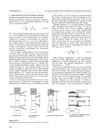
Four possible configurations for the measurement Z ⎜ Peltier 1 ⎟ (6.4.13)
are shown in Fig. 6.4.16a to d. Fig. 6.4.16a is an exam- T ⎝ R 0 ⎠
ple using metal electrodes. With this method, the pos-
sibility of having reaction between the sample and the The electrical conductivity can be calculated
metal electrode at elevated temperatures is of concern. from the sample dimension and R ; and, Seebeck
0
Fig. 6.4.16b is taking one lead of the thermocouple coefficient is simply determined by the equation
wire to measure electromotive force V . In this case, (6.4.12). Thus, the thermal conductivity can be
emf
2
a spring-loaded mechanical contact, using electrically calculated as S /Z.
conducting paste or spot-welding directly onto the Since the transporting phonon can be scattered by
sample, is applied to attach the wire of thermocouple the microstructure (e.g., crystal grain interface and
to the sample. It should watch for the offset voltage, defects) of samples, this reduces thermal conductiv-
which appears at T 0 and can cause inconsistency ity and enhances thermoelectric Figure of Merit. It is
of the measurement. A bad contact produces larger expected to have high thermoelectric Figure of Merit
offset voltage and results in larger error in the meas- for the nano-/microtextured materials. For example,
urement of Seebeck coefficient. Si Ge 20 alloy with an addition of BN or Si N fine
80
3
4
For low-temperature measurements, the use of con- particles (diameter of the particles: 4–20nm) is
ductive pastes or adhesive is most popular to attach reported as having 30% lower thermal conductivity
the lead wire as shown in Fig. 6.4.16d. Because there and 15% increase in the thermoelectric Figure of
Figure 6.4.16
Configurations for the measurement of Seebeck coefficient.
356