
Page 378 - Book Hosokawa Nanoparticle Technology Handbook
P. 378
FUNDAMENTALS CH. 6 EVALUATION METHODS FOR PROPERTIES OF NANOSTRUCTURED BODY
for a circle with a radius of R/2 and a center position respectively. Individual component values can be
of (R/2, 0) [3]. An equivalent circuit for ceramic mate- obtained by selecting appropriate component values
rials is often represented as a complex circuit in which so as to obtain agreement between measured and cal-
parallel circuits are connected in series. An imped- culated impedance plots. The software applicable to
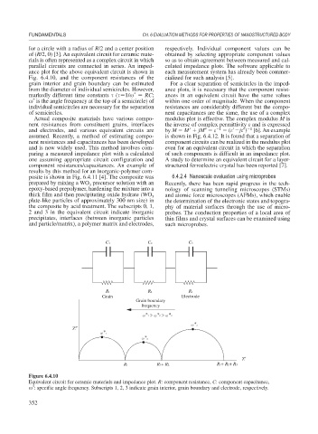
ance plot for the above equivalent circuit is shown in each measurement system has already been commer-
Fig. 6.4.10, and the component resistances of the cialized for such analysis [5].
grain interior and grain boundary can be estimated For a clear separation of semicircles in the imped-
from the diameter of individual semicircles. However, ance plots, it is necessary that the component resist-
*
markedly different time constants ( 1/ RC; ances in an equivalent circuit have the same values
*
is the angle frequency at the top of a semicircle) of within one order of magnitude. When the component
individual semicircles are necessary for the separation resistances are considerably different but the compo-
of semicircles. nent capacitances are the same, the use of a complex
Actual composite materials have various compo- modulus plot is effective. The complex modulus M is
nent resistances from constituent grains, interfaces the inverse of complex permittivity and is expressed
and electrodes, and various equivalent circuits are by M M jM 1 ( j ) 1 [6]. An example
assumed. Recently, a method of estimating compo- is shown in Fig. 6.4.12. It is found that a separation of
nent resistances and capacitances has been developed component circuits can be realized in the modulus plot
and is now widely used. This method involves com- even for an equivalent circuit in which the separation
paring a measured impedance plot with a calculated of such components is difficult in an impedance plot.
one assuming appropriate circuit configuration and A study to determine an equivalent circuit for a layer-
component resistances/capacitances. An example of structured ferroelectric crystal has been reported [7].
results by this method for an inorganic-polymer com-
posite is shown in Fig. 6.4.11 [4]. The composite was 6.4.2.4 Nanoscale evaluation using microprobes
prepared by mixing a WO precursor solution with an Recently, there has been rapid progress in the tech-
3
epoxy-based prepolymer, hardening the mixture into a nology of scanning tunneling microscopes (STMs)
thick film and then precipitating oxide hydrate (WO 3 and atomic force microscopes (AFMs), which enable
plate-like particles of approximately 300 nm size) in the determination of the electronic states and topogra-
the composite by acid treatment. The subscripts 0, 1, phy of material surfaces through the use of micro-
2 and 3 in the equivalent circuit indicate inorganic probes. The conduction properties of a local area of
precipitates, interfaces (between inorganic particles thin films and crystal surfaces can be examined using
and particle/matrix), a polymer matrix and electrodes, such microprobes.
C1 C2 C3
R1 R2 R3
Grain Electrode
Grain boundary
frequency
Z″
Z′
R1 R1+ R2 R1+ R2+ R3
Figure 6.4.10
Equivalent circuit for ceramic materials and impedance plot. R: component resistance, C: component capacitance,
*
: specific angle frequency. Subscripts 1, 2, 3 indicate grain interior, grain boundary and electrode, respectively.
352