Page 376 - Book Hosokawa Nanoparticle Technology Handbook
P. 376

FUNDAMENTALS                           CH. 6 EVALUATION METHODS FOR PROPERTIES OF NANOSTRUCTURED BODY
                                                                 electron depletion layers cover the entire region of
                                                                 these particles. For particles with intermediate sizes,
                                                                 effective electron density changes markedly depend-
                                                                 ing on the amount of adsorbed oxygen. For electrical
                                                                 conduction through a porous structure, as shown in
                                                                 Fig. 6.4.7, electric current flows by crossing electron
                                                                 depletion layers or through paths narrowed by elec-
                                                                 tron depletion layers.  Accordingly, highly resistive
                                                                 electron depletion layers on the surface contribute
                                                                 largely to the overall resistance, and electrical con-
                                                                 ductivity changes markedly depending on particle
                              E c                                size, particle configuration and surface acceptor den-
                                                  E c            sity. When adsorbed water layers exist on the surface
                                     E F                         of insulating particles, electric current flows mainly
                                                         E F     through these layers. Also, in this case, highly con-
                                                                 ductive water layers on the surface contribute largely
                              E
                               V
                                                  E V            to the overall resistance.
                  Figure 6.4.7                                     6.4.2.2 Direct current (DC) measurement
                  Structural schema of porous sintered bodies and their band  By DC measurement, the overall conduction proper-
                  structures. Insulating electron depletion layer is formed on  ties including the contributions of interfaces and sur-
                  grain surface (white region). E : Fermi level, E : energy  faces are measured as described above. Fig. 6.4.9
                                                    C
                                        F
                  level at the bottom of conduction band, E : energy level at  shows general measurement methods for resistivity
                                                V
                                                                                                          1
                  the top of valence band.                       [  m], which is the inverse of conductivity   [S m ]
                                                                 and their features [2]. It also shows the measurement
                                                                 methods for sheet resistance   [ / ] (    /d) used
                                                                                                 s
                                                                                         s
                                                                 for the evaluation of thin films and surfaces. The two-
                                                                 probe and four-probe methods are used for high-
                                                                 resistance and low-resistance samples, respectively.
                                            Particle size (nm)
                      10 17                                      The Van der Pauw method can be applied to the meas-
                                                                 urement of film samples of any shape. In the Van der
                                                                 Pauw method, electrodes are provided at any of the
                                                      100        four positions A, B, C and D on the edge of a film
                      10 15                                      sample, the voltage V CD  between electrodes C and D
                                                                 is measured when an electric current I AB  is made to
                                                                 flow between electrodes A and B, and the resistance
                                                                       is determined using  V /I . The  resistance
                                                                 R
                                                      70
                    neff (cm -3 )  10 13                         R BC,DA  is determined in the same way, and the resis-
                                                                                         CD AB
                                                                  AB,CD
                                                                 tivity of the sample can be obtained from the two
                                                                 resistances. f is the coefficient related to the sample
                                                                 configuration and electrode position, and f   1 when
                                                      50         R      R     . In most cases, measurement is con-
                                                                          BC,DA
                                                                  AB,CD
                      10 11                                      ducted for samples with the shape shown in
                                                                 Fig. 6.4.9f.
                                                                  When leakage current is made to flow in the volt-
                                                                 age measurement circuit, a conductivity larger than
                       10 9
                             T = 400K                 30         the true value is estimated. Accordingly, it is neces-
                                = 8.6                 20         sary for all measurement methods to use a voltmeter
                              r
                               = 1×10 17             10
                            N D                                  with a high internal impedance. It is also necessary to
                            E  = 0.05ev                          maintain the atmosphere (e.g., water vapor pressure
                             D
                                                                 and oxygen partial pressure) unchanged and to con-
                                 10 11    10 12   10 13
                                                                 duct measurement in a dry atmosphere, especially for
                                            -2
                                       Nss (cm )                 high-resistance samples.  The following treatments
                                                                 are effective in improving accuracy: (1) two meas-
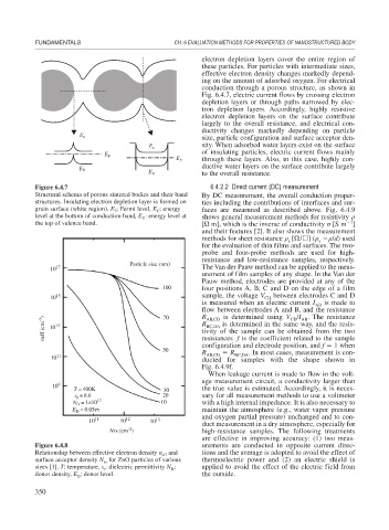
                  Figure 6.4.8                                   urements are conducted in opposite current direc-
                  Relationship between effective electron density n and  tions and the average is adopted to avoid the effect of
                                                     eff
                  surface acceptor density N for ZnO particles of various  thermoelectric power and (2) an electric shield is
                                     ss
                  sizes [1]. T: temperature,   : dielectric permittivity N :  applied to avoid the effect of the electric field from
                                                        D
                                     r
                  donor density, E : donor level.                the outside.
                              D
                  350
   371   372   373   374   375   376   377   378   379   380   381