
Page 372 - Book Hosokawa Nanoparticle Technology Handbook
P. 372
FUNDAMENTALS CH. 6 EVALUATION METHODS FOR PROPERTIES OF NANOSTRUCTURED BODY
Polarization (P) where only is an individual parameter in the cubit
11
phase. Below the T , P appears along the c axis, and
s
C
Remanent ferroelectric BaTiO is transformed to tetragonal
3
polarization P4mm symmetry. In the tetragonal structure, is
ij
(P ) expressed by two parameters of normal to the P s
r
11
‘0’ P s
(along the a axis) and parallel to the P (along the
33
s
c axis) as follows:
⎛ 0 0 ⎞
Electric Field ⎜ 11 ⎟
0 0 (6.4.4)
(E) ij ⎜ 11 ⎟
0 ⎜ ⎝ 0 0 ⎠ ⎟
33
Coercive Field The dielectric properties in a frequency range from kHz
(E ) to GHz of BaTiO are known to be governed by ionic
c
3
P s polarization (polarization originating from the displace-
ments of the constituent ions). Recently, the dynamics
‘1’ of polar nanoregions (ferroelectric nanodomains) that
are classified into orientational polarization have been
revealed to play an essential role in dielectric properties
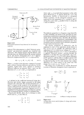
Figure 6.4.2
Polarization hysteresis loop observed for ferroelectric for perovskite ferroelectrics [10].
materials. The electric properties of dielectrics can be
explained in view of the equivalent circuit shown in
Fig. 6.4.3a. Let us consider the dielectrics with a
induced. This phenomenon is called “dielectric polar- capacitance of C to which an ac voltage of V V e j t
0
ization” and polarized materials are classified into with an angular frequency of 2 f (f is frequency)
dielectrics. The charged species of point defects, ions is applied. Electrical current I passing through the
and electrons are displaced from the neutral position dielectrics is divided into two components: one is dis-
–2
by E, and electric polarization P (C cm ) appears. placement current I ( j CV) with a phase difference
C
–2
Dielectric displacement D (C m ) is expressed by: of 90 against V, and the other is in-phase current with
V due to conductance G (resistance R 1/G). As can
D 0
ij
E 0
E P i (6.4.1) be depicted in Fig. 6.4.3b, total current I has a phase
j
j
i
difference of with respect to the ideal case that
Where, (scalar) is the dielectric constant of vacuum energy loss is zero, i.e., I 0 and I I .
0
C
R
and (tensor) denotes dielectric permittivity. In this The energy loss of dielectrics is usually discussed
ij
equation, higher-order terms related to nonlinear in terms of dielectric dissipation factor expressed as
dielectric behavior are ignored. Here, i and j are the
directions of 1, 2, or 3, and is expressed as: | I | G
ij
tan R (6.4.5)
⎛ ⎞ | I C | C
⎜ 11 12 13 ⎟
⎜ 21 22 23 ⎟ (6.4.2)
ij
⎜ ⎝ 31 32 ⎠ ⎟
33
I
is defined as the coefficient between E along the j
ij
direction and electric charge generated in the plane I =GV I =j CV I c I
R
c
normal to the i direction. The crystal orientation of 1, 2
and 3 is based on the notation of the principal axis,
which is different from the normal one defined for indi- C δ
vidual crystallographic symmetry. Equation (6.4.2) is R
simplified for the perovskite-type ferroelectrics and the =1/G
case of tetragonal BaTiO (P4mm) is explained here. V
3
Paraelectric BaTiO above the T belongs to cubic j t I R
C
3
0
Pm3 m and its is described as V=V e
ij
(a) Equivalent circuit (b) Phase of voltage and current
⎛ 0 0 ⎞
⎜ 11 ⎟ Figure 6.4.3
0 11 0 ⎟ (6.4.3)
⎜
ij
⎜ ⎝ 0 0 ⎠ ⎟ (a) Equivalent circuit and (b) phase of voltage and current
of condensers.
11
346