
Page 388 - Book Hosokawa Nanoparticle Technology Handbook
P. 388
FUNDAMENTALS CH. 6 EVALUATION METHODS FOR PROPERTIES OF NANOSTRUCTURED BODY
15.0
⏐Z″⏐(Ω) 10.0
5.0
0
0 5.0 10.0 15.0
⏐Z′⏐(Ω)
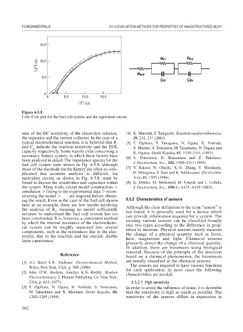
Figure 6.5.8
Cole–Cole plot for the fuel cell system and the equivalent circuit.
sum of the DC resistivity of the electrolyte solution, [4] K. Matsuda, I. Taniguchi: Kagakukougakuronbunnsyu,
the separator and the current collector. In the case of a 29, 232–237 (2003).
typical electrochemical reaction, it is believed that R c [5] T. Ogihara, T. Yanagawa, N. Ogata, K. Yoshida,
and C indicate the reaction resistivity and the EDL Y. Mizuno, S. Yonezawa, M. Takashima, N. Nagata and
d
capacity respectively. Some reports exist concerning a K. Ogawa: Denki Kagaku, 61, 1339–1341 (1993).
secondary battery system, in which these factors have [6] S. Yonezawa, K. Kanamura and Z. Takehara:
been analyzed in detail. The impedance spectra for the
fuel cell system were shown in Fig. 6.5.8, although J. Electrochem. Soc., 142, 3309–3313 (1995).
those of the electrode for the battery are often so com- [7] Y. Takasu, N. Ohashi, X.-G. Zhang, Y. Murakami,
plicated that accurate analysis is difficult. An H. Minagawa, S. Sato and K. Yahikozawa: Electrochim.
equivalent circuit, as shown in Fig. 6.5.8, must be Acta, 41, 1595 (1996).
found to discuss the resistivities and capacities within [8] K. Dokko, M. Mohamed, M. Umeda and I. Uchida,
the system. Many trials, circuit model construction J. Electrochem. Soc., 150(4), A425–A429 (2003).
simulation fitting to the experimental data recon-
structing the model . . . are required before obtain-
ing the result. Even in the case of the fuel cell shown 6.5.2 Characteristics of sensors
here as an example, there are few results involving
the analysis of R , meaning no model sufficiently Although the clear definition to the term “sensor” is
c
accurate to understand the fuel cell system has yet not found, it is generally used for a device which
been constructed. It is, however, a convenient method can provide information required for a system. The
by which the internal resistance of the electrochemi- existing various sensors can be classified broadly
cal system can be roughly separated into several into two types according to the difference in prop-
components, such as the resistances due to the elec- erties to measure. Physical sensors mainly measure
trolyte, due to the reaction and the electric double the change of a physical quantity such as force,
layer capacitance. heat, magnetism and light. Chemical sensors
primarily detect the change of a chemical quantity.
In addition, there are biosensors using biological
material. Because of the principle of the detection
Reference
based on a chemical phenomenon, the biosensors
are usually classified as the chemical sensors.
[1] A.J. Bard, L.R. Faulkner: Electrochemical Method,
The sensors are required to have various functions
Wiley, New York, USA, p. 500 (1980).
for each application. In most cases the following
[2] John O’M. Bockris, Amulya K.N. Reddy: Modern
characteristics are needed.
Electrochemistry 2, Plenum Publishing Co. New York,
USA, p. 632 (1977). 6.5.2.1 High sensitivity
[3] T. Ogihara, N. Ogata, K. Yoshida, S. Yonezawa, In order to avoid the influence of noise, it is desirable
M. Takashima and N. Mizutani: Denki Kagaku, 66, that the sensitivity is high as much as possible. The
1202–1205 (1998). sensitivity of the sensors differs in expression in
362