
Page 407 - Book Hosokawa Nanoparticle Technology Handbook
P. 407
6.9 PROPERTIES OF GAS PERMEATION AND SEPARATION MEMBRANES FUNDAMENTALS
the non-porous polymer membrane with a polymer Membranes are used to separate oxygen and nitro-
chain gap from 0.3 to 1 nm induced by thermal vibra- gen from the air for medical and combustion fuel
tion. The effective size of the gas molecules for per- applications. The volume flow rate of oxygen enriched
meation and separation is extremely small, e.g., air required for the medicals purposes (40% O ) is
2
0.234 nm for the smallest hydrogen, 0.323 and 4–8 L per min, while it needs air containing 30% O 2
0.363 nm for carbon dioxide and nitrogen respec- for combustion applications as much as we can.
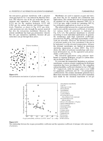
tively. Therefore, as shown in Fig. 6.9.1, gas mole- The relationship between the oxygen permeability
cules permeate not only through the porous material coefficient and the separation coefficient of nitrogen
but also the non-porous membrane. However, the for various kinds of polymers is indicated in
porous membrane has high gas permeation velocity Fig. 6.9.2 [3]. The polymer membrane is selected
but low gas separation capability, because all gas according to each individual application. In general,
molecules can go through these pores. the membranes with high separation coefficient,
presented by PO /PN , and high permeability coeffi-
2
2
cient are desirable. However, the thermal resistance
of polymer needs to be first considered if the gas to
be separated is at the elevated temperatures, because
Polymer membrane
the polymer membranes are limited to maximum
operating temperature at about 150 C. Fig. 6.9.2
shows the effect of polymer morphology and struc-
tural deformation etc. on the separation and perme-
ability coefficients [3].
The industrial applications using polymer mem-
branes to separate hydrogen, oxygen or carbon diox-
ide are listed in Table 6.9.1 [4].
To overcome the temperature limitation on polymer
membranes, a porous ceramic membrane for hydrogen
separation has been investigated [5]. The separation
and permeability coefficient obtained so far is 500 and
10 8 respectively, while the target value is over 1,000
for separation coefficient and 10 7 for permeability
coefficient [6]. The ceramic membrane generally has a
Figure 6.9.1 three-layer structure consisting of the active separation
Gas-permeation mechanism of polymer membrane. layer made by the chemical deposition or sol–gel
1.Polyethylene terephthalate
2.Nylon6
Oxygen partial pressure / nitrogen partial pressure 7.Acetylcellulose
3.Polyvinyl chloride
4.Polycarbonate
5.Polyethylene
6.Polypropylene
8.Polydimethylsiloxane
-Polycarbonate block copolymer
9.Polydimethylsiloxane
(Silicone rubber)
10.Poly(1-(Trimethylsilyl)-1-Propine)
11.Poly(4-Methylpentene-1)
12.Poly phenylene
13.Polyvinyl acetate
14.Teflon FEP
15.Natural rubber
16.Polybutadiene
17.Ethylcellulose
18.Polystyrene
19.Butyl rubber
2
Oxygen permeability coefficient (cc(STP) · cm/cm · sec · cmHg) 20.Nitrocellulose
Figure 6.9.2
The relationship between the oxygen permeability coefficient and the separation coefficient of nitrogen with various kind
of polymers.
381