
Page 439 - Book Hosokawa Nanoparticle Technology Handbook
P. 439
7.4 REMOVAL OF NANOPARTICLES FUNDAMENTALS
7.4.3 Removal of nanoparticles in liquid One of the major factors limiting the use of mem-
brane filtration is membrane fouling, resulting in a
There are two types of methods that differ in the way dramatic decline in flux with time of operation.
the nanoparticles in liquid are collected. The first To account for the membrane fouling, the resistance-
group, called membrane filtration, constrains the par- in-series model is frequently employed. The resist-
ticles by a membrane, and the liquid is allowed to ance model becomes
flow freely through the membrane. In the second
group of ultracentrifugation, the liquid is constrained dv p p
in a rotating vessel, and the particles move freely u (7.4.1)
1
within the liquid by an external field of acceleration d R t ( R bm R + R )
c
cp
caused by ultracentrifugal field. These methods have
been quite extensively used in separation of macro- where u is the permeate flux, v the filtrate volume
1
molecules and molecules from liquid, and they are per unit membrane area, the filtration time, p the
recently becoming important also in separation of applied transmembrane pressure, the viscosity of
nanoparticles from liquid. the permeate, R the total resistance, R bm the resistance
t
of the membrane per se plus the clogging of the mem-
7.4.3.1 Fouling mechanism in membrane filtration brane pores, R the resistance of the filter cake, and
c
In pressure-driven membrane filtration processes, the R cp the resistance of the concentration polarization
pressure gradient across the membrane would force layer. Significance of each resistance in membrane
solvent and smaller species through the pores of filtration is as follows.
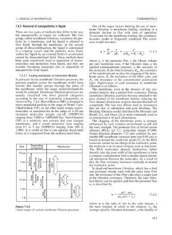
the membrane, while the larger molecules/particles The membrane, even in the absence of any sus-
would be retained. Membrane filtration processes are pended particle, has a natural flow resistance. During
usually classified into three general categories membrane filtration, particles become attached to the
according to the size of separating components, as pore channel of the membrane thereby reducing the
shown in Fig. 7.4.6. Microfiltration (MF) is designed to flow channel dimension, or pores become blocked off
retain suspended particles in the range of 50 nm–5 m. completely. The last two effects lead to resistances
Ultrafiltration (UF), on the other hand, retains macro- that are due to adsorption and pore blocking. The
molecules or nanoparticles in the range of 5–50 nm blocking filtration model introduced by Hermans and
(nominal molecular weight cut-off (NMWCO) Bredée [1], and Grace [2] is most commonly used as
ranging from 5,000 to 5,000,000 Da). Nanofiltration an interpretation of such phenomena.
(NF) is a relatively new process that uses charged The clogging of the membrane pores is strongly
membranes, and it covers molecular sizes ranging influenced by such solution environment as pH and
from 0.1 to 5 nm (NMWCO ranging from 200 to the ionic strength. The permeate flux of bovine serum
1,000). It is useful in that it can separate dissociated albumin (BSA) (pI 5.1, molecular weight 67,000,
forms of a compound from the undissociated form. Stokes–Einstein diameter 3.55 nm) solution by per-
meable MF membrane (nominal pore size 0.05 m) is
lowest at around the isoelectric point [3]. As the BSA
molecule carries no net charge at the isoelectric point,
Separating
Size Membrane the molecule is in its most compact state at that point.
component
The BSA molecules deposit themselves rather
10 μm densely onto the pore walls of the membrane to form
a compact configuration with a smaller lateral electri-
Bacteria cal interaction between the molecules. As a result of
1 μm Clay Emulsion Microfiltration (MF) this, the flow resistance increases markedly at around
the isoelectric point.
In dead-end membrane filtration, which has a feed
100 nm and permeate stream, each with the same mass flow
Virus Albumin rate, the resistance of the filter cake plays a major part
in the filtration resistance. Therefore, the cake filtra-
10 nm Humin Ultrafiltration (UF) tion theory can be applied, and thus the permeate flux
u is described by
1 nm Nanofiltration (NF) 1
Ions u p 1 ( ms) (7.4.2)
1
av
m
1 Å sv ( v )
where m is the ratio of wet to dry cake masses, s
Figure 7.4.6 the mass fraction of solids in the solution, av the
Useful ranges of various membrane filtration processes. average specific filtration resistance, the density of
413