
Page 577 - Book Hosokawa Nanoparticle Technology Handbook
P. 577
30 NOZZLE-FREE INKJET TECHNOLOGY APPLICATIONS
X-Y stage
Vessel and
Ultra sonic vibrator
Inkjet part
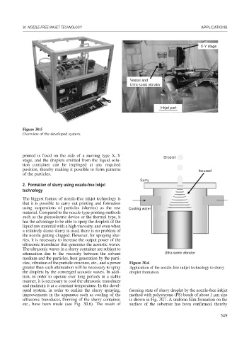
Figure 30.5
Overview of the developed system.
printed is fixed on the side of a moving type X–Y Droplet
stage, and the droplets emitted from the liquid solu-
tion container can be impinged at any required
position, thereby making it possible to form patterns focused
of the particles.
Surry
2. Formation of slurry using nozzle-free inkjet
technology
The biggest feature of nozzle-free inkjet technology is
that it is possible to carry out printing and formation
using suspensions of particles (slurries) as the raw Cooling water
material. Compared to the nozzle-type printing methods
such as the piezoelectric device or the thermal type, it
has the advantage to be able to spray the droplets of the
liquid raw material with a high viscosity, and even when
a relatively dense slurry is used, there is no problem of
the nozzle getting clogged. However, for spraying slur-
ries, it is necessary to increase the output power of the
ultrasonic transducer that generates the acoustic waves.
The ultrasonic waves in a slurry container are subject to
attenuation due to the viscosity between the solvent Ultra sonic vibrator
medium and the particles, heat generation by the parti-
cles, vibration of the particle structure, etc., and a power Figure 30.6
greater than such attenuation will be necessary to spray Application of the nozzle-free inkjet technology to slurry
the droplets by the converged acoustic waves. In addi- droplet formation.
tion, in order to operate over long periods in a stable
manner, it is necessary to cool the ultrasonic transducer
and maintain it at a constant temperature. In the devel-
oped system, in order to realize the slurry spraying, forming state of slurry droplet by the nozzle-free inkjet
improvements in the apparatus such as cooling of the method with polystyrene (PS) beads of about 1 m size
ultrasonic transducer, thinning of the slurry container, is shown in Fig. 30.7. A uniform film formation on the
etc., have been made (see Fig. 30.6). The result of surface of the substrate has been confirmed, thereby
549