
Page 87 - Nanotechnology an introduction
P. 87
optical waveguides. In other words the nanoregime of photonics is the regime of the near zone and concerns processes taking place within the
evanescent field. The term can also be used to describe light sources based on nano-objects (quantum wells in the form of plates, wires or
particles) and nanoparticle-based photoelectrochemical solar energy converters (cf. Figure 7.24).
Semiconductor lasers, in which a voltage is applied across a semiconductor crystal (which in effect constitutes a Fabry–Perot cavity) to create a
nonequilibrium population distribution of electrons and holes, whose luminescent recombination generates photons stimulating further emission,
were already in existence when Dingle and Henry showed that using quantum wells as the active lasing medium would result in more efficient lasers
with lower threshold currents [41], essentially because quantum confinement of the charge carriers and the optical modes enhances carrier–
radiation interaction; moreover the lasing wavelength could be tuned by changing the thickness of the layers: quantum well lasers are made from
alternating ultrathin layers of wider and narrower band gap semiconductors (for example, n-AlGaAs and GaAs, respectively). Improvements in the
technology of ultrathin film fabrication, especially with the introduction of techniques such as molecular beam epitaxy (MBE) (Section 6.3.1),
enabled quantum well lasers to become a reality.
Reduction of the dimensionality from two to one (quantum wires) and to zero should lead to further improvements (even higher gain and lower
threshold current than quantum well lasers). The carriers are confined in a very small volume and population inversion occurs more easily, leading to
lower threshold currents for lasing. Furthermore, the emission wavelength can be readily tuned by simply varying the dimensions of the dot (or well).
The main difficulty is to ensure that the dots comprising a device are uniformly sized. If not, the density of states is smeared out and the behavior
reverts to bulk-like, negating the advantage of the zero-dimensional confinement. Early attempts to produce quantum dots a few tens of nanometers
in diameter using electron beam lithography followed by the usual semiconductor processing (etching, see Section 8.1.1) were bedevilled by
damage and contamination introduced by the processing. An important advance came through the exploitation of frustrated wetting (Stranski–
Krastanov growth): lattice mismatch between the deposited layer and the substratum results in strain, which was found to be relieved by the
spontaneous formation of monodisperse islands (Section 8.1.2).
Microcavities have the potential for fabricating ultrahigh-Q and ultralow threshold lasers. Cylindrical or spherical microcavities are particularly
interesting in that they have extremely low loss “whispering gallery” modes (WGM), which occur when light circumnavigating the cavity is trapped by
total internal reflexions and constructively interferes with itself. To construct a laser based on a microcavity it is surrounded by gain medium and
pumped by an external light source. The lower limit of miniaturization is exemplified by the laser oscillation demonstrated with a single atom in an
10
optical resonator. Threshold pump energies of the order of 100 μJ have been demonstrated. Quality factors in excess of 10 can be routinely
obtained.
7.8. Mechanical Devices
3
The spring constant (stiffness) k of a nanocantilever varies with its characteristic linear dimension l, and its mass m as l . Hence the resonant
frequency of its vibration
(7.22)
varies as 1/l. This ensures a fast response—in effect, nanomechanical devices are extremely stiff. Since the figure of merit (quality factor) Q equals
ω divided by the drag (friction) coefficient, especially for devices operating in a high vacuum Q can be many orders of magnitude greater than the
0
values encountered in conventional devices. On the other hand, under typical terrestrial operating conditions water vapor and other impurities may
condense onto moving parts, increasing drag due to capillary effects (cf. Figure 3.1), and generally degrading performance.
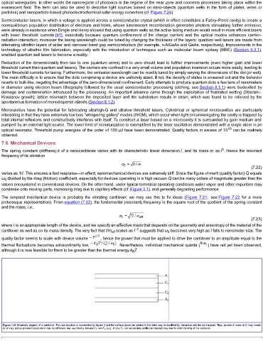
The simplest mechanical device is probably the vibrating cantilever; we may use this to fix ideas (Figure 7.21; see Figure 7.22 for a more
picturesque representation). From equation (7.22), the fundamental (resonant) frequency is the square root of the quotient of the spring constant
and the mass, i.e.,
(7.23)
where l is an appropriate length of the device, and we specify an effective mass that depends on the geometry and anisotropy of the material of the
−2
cantilever as well as on its mass density. The very fact that l/m scales as l suggests that ω becomes very high as l falls to nanometer size. The
eff
0
quality factor seems to scale with device volume , hence the power that must be applied to drive the cantilever to an amplitude equal to the
thermal fluctuations becomes extraordinarily low, . Nevertheless, individual mechanical quanta ( ) have not yet been observed,
although it is now feasible for them to be greater than the thermal energy k T.
B
Figure 7.21 Schematic diagram of a cantilever. The core structure is represented by layers C and the surface layers are labeled A; the latter may be modified by interaction with the environment. Thus, accrual of mass on C may create
A, or very porous pre-existing structure may be stiffened. Any asymmetry between C 1 and C 2 (e.g., if only C 1 can accumulate additional material) may lead to static bending of the cantilever.