
Page 322 - Op Amps Design, Applications, and Troubleshooting
P. 322
300 SIGNAL PROCESSING CIRCUITS
/\ /\
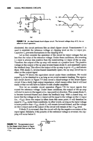
FIGURE 7.8 An ideal biased shunt-clipper circuit. The forward voltage drop of D, has no
effect on circuit operation.
eliminated, the circuit performs like an ideal clipper circuit. Potentiometer PI is
used to establish the reference voltage or clipping level on the (+) input pin.
Capacitor Q prevents fluctuations in the clipping level.
Let us first consider the operation of the circuit for input voltages that are
less than the value of the reference voltage. Under these conditions, the inverting
(-) input is always less positive than the noninverting (+) input of the op amp.
Therefore, the output of the op amp will remain at a positive level. The positive
voltage on the output of the op amp reverse-biases diode Dj and essentially opens
the feedback loop. This allows the output of the op amp to go to + V SAT and remain
there. With diode D! reverse-biased (essentially open), the op amp circuit has no
effect on the output signal.
Figure 7.9 shows the equivalent circuit under these conditions. We would
expect V Q to be identical to Vj as long as we avoid excessive loading. The equiva-
lent circuit shown in Figure 7.9 does reveal a disadvantage of the shunt-clipper
circuit: It has a fairly high output impedance, which means either that it will load
easily or that we will have to follow it with a buffer amplifier.
Now let us consider circuit operation (Figure 7.8) for input signals that
exceed the reference voltage. Under these conditions, the output of the op amp
will start to move in the negative (i.e., less positive) direction. This causes diode D l
to become forward-biased and doses the feedback loop. With a closed loop, we
know that the voltage on the (-) input will be equal to the voltage on the (+) input
(i.e., +V REF). Since the output is taken from this same point, it will therefore be
equal to + V REF under these conditions. In other words, as long as the input voltage
is more positive than +V REf, diode Dj will remain forward-biased, and the voltage
on the (-) input and at the output of the circuit will remain at the +VK& level.
If diode DI is reversed, then the circuit will clip the negative excursion of the
input signal. Similarly, if the polarity of the reference voltage is reversed, the clip-
ping will occur below 0.
FIGURE 7.9 The equivalent circuit
for the clipper circuit shown in Figure
7.8 for input signals that are less than