
Page 325 - Op Amps Design, Applications, and Troubleshooting
P. 325
Ideal Biased Clipper 303
7.3.3 Practical Design Techniques
We are now ready to design an ideal biased shunt-clipper circuit similar to the one
shown in Figure 7.8. We will design to achieve the following performance goals:
1. Clipping levels +3 to-3 volts
2. Polarity of clipping Negative peaks clipped
3. Input frequency 100 hertz to 3 kilohertz
4. Minimum input impedance 8kilohms
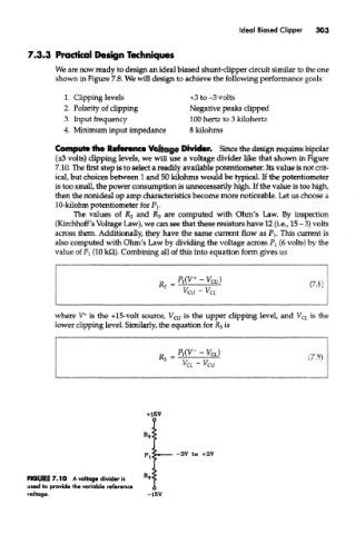
Compute the Reference Voltage Divider. Since the design requires bipolar
(±3 volts) clipping levels, we wiH use a voltage divider like that shown in Figure
7.10. The first step is to select a readily available potentiometer. Its value is not crit-
ical, but choices between 1 and 50 kilohms would be typical. If the potentiometer
is too small, the power consumption is unnecessarily high. If the value is too high,
then the nonideal op amp characteristics become more noticeable. Let us choose a
10-kilohm potentiometer for P^
The values of R 2 and R 3 are computed with Ohm's Law. By inspection
(Kirchhoff's Voltage Law), we can see that these resistors have 12 (i.e., 15 - 3) volts
across them. Additionally, they have the same current flow as Pj. This current is
also computed with Ohm's Law by dividing the voltage across P l (6 volts) by the
value of PI (10 kQ). Combining all of this into equation form gives us
+
where V is the +15-volt source, V cu is the upper clipping level, and V CL is the
lower clipping level. Similarly, the equation for R 3 is
FIGURE 7.10 A voltage divider is
used to provide the variable reference
voltage. -15V