
Page 327 - Op Amps Design, Applications, and Troubleshooting
P. 327
Ideal Biased Clipper 305
We will select a standard value of 1.0 microfarad for our circuit.
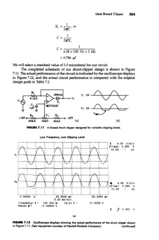
The completed schematic of our shunt-clipper design is shown in Figure
7.11. The actual performance of the circuit is indicated by the oscilloscope displays
in Figure 7.12, and the actual circuit performance is compared with the original
design goals in Table 7.2.
FIGURE 7.11 A biased shunt clipper designed for variable clipping levels.
Low Frequency, Low Clipping Level
FIGURE 7.12 Oscilloscope displays showing the actual performance of the shunt clipper shown
in Figure 7.11. (Test equipment courtesy of Hewlett-Packard Company.) (conffnued)