
Page 317 - Op Amps Design, Applications, and Troubleshooting
P. 317
Ideal Rectifier Circuits 295
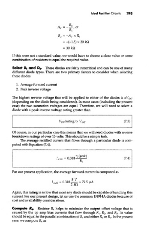
If this were not a standard value, we would have to choose a close value or some
combination of resistors to equal the required value.
Select Dj and 02. These diodes are fairly noncritkal and can be one of many
different diode types. There are two primary factors to consider when selecting
these diodes:
1. Average forward current
2. Peak inverse voltage
The highest reverse voltage that will be applied to either of the diodes is ±V SAT
(depending on the diode being considered). In most cases (including the present
case) the two saturation voltages are equal. Therefore, we will need to select a
diode with a peak inverse voltage rating greater than
Of course, in our particular case this means that we will need diodes with reverse
breakdown ratings of over 13 volts. This should be a simple task.
The average rectified current that flows through a particular diode is com-
puted with Equation (7.4).
For our present application, the average forward current is computed as
Again, this rating is so low that most any diode should be capable of handling this
current. For our present design, let us use the common 1N914A diodes because of
cost and availability considerations.
Compute £*. Resistor JR 4 helps to minimize the output offset voltage that is
caused by the op amp bias currents that flow through R lf R 2, and R 3. Its value
should be equal to the parallel combination of RI and either R 2 or R 3. In the present
case, we compute R 4 as