
Page 421 - Op Amps Design, Applications, and Troubleshooting
P. 421
Nonidea! AC Characteristics 397
As briefly mentioned earlier in this section, each of the internal stages of an
op amp have frequency and phase characteristics similar to the RC sections pre-
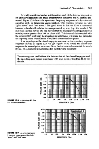
sented. Figure 10.9 shows the open-loop frequency response of a hypothetical
amplifier with no frequency compensation. This response presents us with
"good news" and "bad news." The good news is that we have a substantial
increase in bandwidth relative to a compensated op amp (e.g., the standard 741
shown as a dotted curve). The bad news is that the multiple break frequencies will
certainly cause greater than 180° of phase shift. This internal shift coupled with
the inherent 180° shift from the inverting input terminal will make this particular
op amp very prone to oscillation. Now, let us determine how prone.
If we superimpose the closed-loop gain response on the open-loop response
originally shown in Figure 10.9, we get Figure 10.10, where the closed-loop
responses for several gains are shown. Now, the important characteristic for stabil-
ity (i.e., no oscillations) is summarized in the following statement:
To ensure against oscillations, the intersection of the closed-loop gain and
the open-loop gain curves must occur with a net slope of less than 40 dB per
decade.
FIGURE 10.8 A two-stage RC filter
hos a cumulative effect.
Hypothetical &
Uncompenaaied
FIGURE 10.9 An uncompensated
frequency response provides both
"good" and "bad" news.