
Page 422 - Op Amps Design, Applications, and Troubleshooting
P. 422
398 NONIDEAL OP AMP CHARACTERISTICS
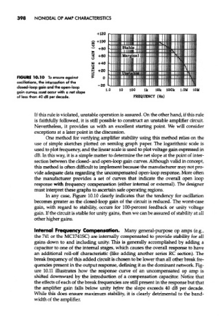
FIGURE 10.10 To ensure against
oscillations, the intersection of the
closed-loop gain and the open-loop
gain curves must occur with a net slope
of less than 40 dB per decade.
If this rule is violated, unstable operation is assured. On the other hand, if this rule
is faithfully followed, it is still possible to construct an unstable amplifier circuit.
Nevertheless, it provides us with an excellent starting point. We will consider
exceptions at a later point in the discussion.
One method for verifying amplifier stability using this method relies on the
use of simple sketches plotted on semilog graph paper. The logarithmic scale is
used to plot frequency, and the linear scale is used to plot voltage gain expressed in
dB. In this way, it is a simple matter to determine the net slope at the point of inter-
section between the closed- and open-loop gain curves. Although valid in concept,
this method is often difficult to implement because the manufacturer may not pro-
vide adequate data regarding the uncompensated open-loop response. More often
the manufacturer provides a set of curves that indicate the overall open loop
response with frequency compensation (either internal or external). The designer
must interpret these graphs to ascertain safe operating regions.
In any case, Figure 10.10 clearly indicates that the tendency for oscillation
becomes greater as the closed-loop gain of the circuit is reduced. The worst-case
gain, with regard to stability, occurs for 100-percent feedback or unity voltage
gain. If the circuit is stable for unity gains, then we can be assured of stability at all
other higher gains.
Internal Frequency Compensation. Many general-purpose op amps (e.g.,
the 741 or the MC1741SC) are internally compensated to provide stability for all
gains down to and including unity. This is generally accomplished by adding a
capacitor to one of the internal stages, which causes the overall response to have
an additional roll-off characteristic (like adding another series RC section). The
break frequency of this added circuit is chosen to be lower than all other break fre-
quencies present in the output response, defining it as the dominant network. Fig-
ure 10.11 illustrates how the response curve of an uncompensated op amp is
shifted downward by the introduction of a compensation capacitor. Notice that
the effects of each of the break frequencies are still present in the response but that
the amplifier gain falls below unity before the slope exceeds 40 dB per decade.
While this does ensure maximum stability, it is clearly detrimental to the band-
width of the amplifier.