
Page 215 - Optofluidics Fundamentals, Devices, and Applications
P. 215
190 Cha pte r Ei g h t
is composed of a flexible PDMS lens, silicon conducting ring, and
silicon heater [96]. The mismatching of the coefficient of thermal
expansion and stiffness between PDMS and silicon leads to defor-
mation of polymer lens during heating, so as to further change its
focal length. The difficulty to control thermal expansion of a large
area limits the aperture to hundreds of micrometers for any practi-
cal design. Pneumatically actuated lenses do not bear these limita-
tions and are discussed in further details as follows.
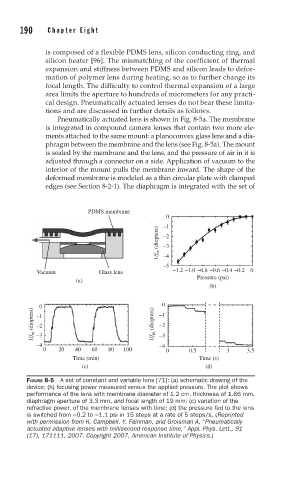
Pneumatically actuated lens is shown in Fig. 8-5a. The membrane
is integrated in compound camera lenses that contain two more ele-
ments attached to the same mount: a planoconvex glass lens and a dia-
phragm between the membrane and the lens (see Fig. 8-5a). The mount
is sealed by the membrane and the lens, and the pressure of air in it is
adjusted through a connector on a side. Application of vacuum to the
interior of the mount pulls the membrane inward. The shape of the
deformed membrane is modeled as a thin circular plate with clamped
edges (see Section 8-2-1). The diaphragm is integrated with the set of
PDMS membrane
0
–1
1/f m (diopters) –2
–3
–4
–5
Vacuum Glass lens –1.2 –1.0 –0.8 –0.6 –0.4 –0.2 0
Pressure (psi)
(a)
(b)
0 –1 0
1/f m (diopters) –1 1/f m (diopters) –2
–2
–3
–4 –3
–4
0 20 40 60 80 100 0 0.5 3 3.5
Time (min) Time (s)
(c) (d)
FIGURE 8-5 A set of constant and variable lens [71]: (a) schematic drawing of the
device; (b) focusing power measured versus the applied pressure. The plot shows
performance of the lens with membrane diameter of 1.2 cm, thickness of 1.66 mm,
diaphragm aperture of 3.3 mm, and focal length of 19 mm; (c) variation of the
refractive power, of the membrane lenses with time; (d) the pressure fed to the lens
is switched from −0.2 to −1.1 psi in 15 steps at a rate of 5 steps/s. (Reprinted
with permission from K. Campbell, Y. Fainman, and Groisman A, “Pneumatically
actuated adaptive lenses with millisecond response time,” Appl. Phys. Lett., 91
(17), 171111, 2007. Copyright 2007, American Institute of Physics.)