
Page 217 - Optofluidics Fundamentals, Devices, and Applications
P. 217
192 Cha pte r Ei g h t
Flaps
8
Rotation angle (degrees) 6 4
0 2
Frames 10 mm 0 0.5 1 1.5 2
Diffraction gratings Pressure (psi)
(a) (c)
0.7 0.6
0.6 0.4
0.5 ΔX/X 0.2
Frame Hinge Flaps Cavity Indentation
ΔX/X 0.4 0 0 0.5 1 1.5
0.3 Pressure (psi)
0.2
0.1
2 mm 0
Via PDMS Glass slide 0 1 2 3 4 5 6 7 8
support h (mm)
(b) (d)
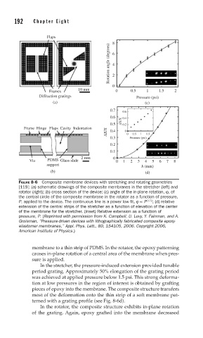
FIGURE 8-6 Composite membrane devices with stretching and rotating geometries
[119]: (a) schematic drawings of the composite membranes in the stretcher (left) and
rotator (right); (b) cross section of the device; (c) angle of the in-plane rotation, ϕ, of
the central circle of the composite membrane in the rotator as a function of pressure,
P, applied to the device. The continuous line is a power low fi t, ϕ ∝ P 0.72 ; (d) relative
extension of the central strips of the stretcher as a function of elevation of the center
of the membrane for the stretcher. (inset) Relative extension as a function of
pressure, P. (Reprinted with permission from K. Campbell, U. Levy, Y. Fainman, and A.
Groisman, “Pressure-driven devices with lithographically fabricated composite epoxy-
elastomer membranes,” Appl. Phys. Lett., 89, 154105, 2006. Copyright 2006,
American Institute of Physics.)
membrane to a thin strip of PDMS. In the rotator, the epoxy patterning
causes in-plane rotation of a central area of the membrane when pres-
sure is applied.
In the stretcher, the pressure-induced extension provided tunable
period grating. Approximately 50% elongation of the grating period
was achieved at applied pressure below 1.5 psi. This strong deforma-
tion at low pressures in the region of interest is obtained by grafting
pieces of epoxy into the membrane. The composite structure transfers
most of the deformation onto the thin strip of a soft membrane pat-
terned with a grating profile (see Fig. 8-6d).
In the rotator, the composite structure exhibits in-plane rotation
of the grating. Again, epoxy grafted into the membrane decreased